



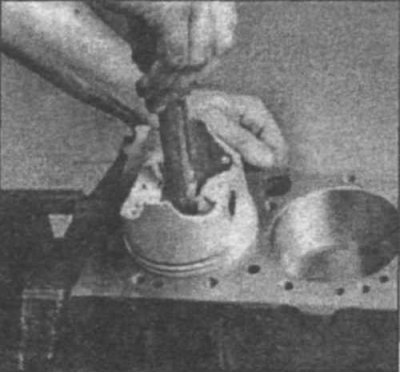
22.2 When checking the end clearance of the piston ring, it must be installed perpendicular to the cylinder walls (to do this, lower the ring into the cylinder using a piston)
2. Install the upper compression ring into the first cylinder (22.2) and lower it to the very bottom of the cylinder.
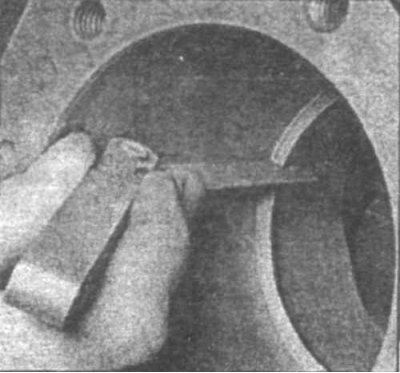
22.3a Measure the ring end gap using a set of feeler gauges
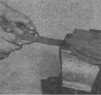
22.3b If the end clearance is too small, clamp the file in a vice and file down the ends of the ring (sliding the ring along the file from the outside to the inside)
3. Measure the end clearance using a set of feeler gauges (22.3a). If the clearance is too small, remove the ring from the cylinder and grind its ends (22.3b). If the clearance is too large, check that it does not exceed 0.9 mm.
4. Check the end clearance of the remaining rings in the same manner.
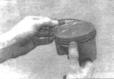
22.5a Install the spacer ring into the groove
(Article reprinted from the website MITSUBISHIMAN)
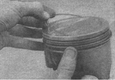
22.5b Do not use a piston ring installation tool when installing oil scraper rings
5. When installing the rings on the piston, the oil scraper ring is installed first. It consists of three elements. Install the spacer ring in the groove (22.5a). Then, using your fingers, without using a tool for installing piston rings, install the lower and upper oil scraper rings (22.5b). Check that the upper and lower rings move smoothly in the groove.
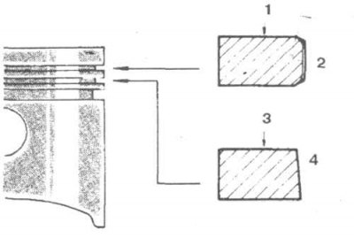
22.6a Compression rings No.1 and 2 have different cross-sections - do not mix them up and install them with the mark facing up.
1. Marks; 2. Surface with chamfers; 3. Marks; 4. Beveled edge
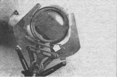
22.6b Install the compression rings using a piston ring installation tool - the mark (indicated by the arrow) should be facing upwards
6. Then, using the piston ring installation tool, install the second compression ring into the middle groove on the piston. It must be installed with the mark facing up (22.6a and 22.6b).
Note: On 1.8L Turbo and 2.0L Cordia/Tredia engines, compression ring thickness varies depending on engine type. See the following chart.
| Ring | Engine | Ring thickness | Identification mark |
| Top | 1.8L | 1.5 mm | T |
| 2.0L | 2.0 mm | N | |
| Bottom | 1.8L | 1.5 mm | 2T |
| 2.0L | 2.0 mm | N |
7. Install the upper compression ring in the same manner with the mark facing up. Do not confuse the upper and second compression rings.
8. Install the rings on the remaining pistons.