



2. Lay out the piston/connecting rod assemblies and new rings so that the ring sets will match the pistons and cylinder liners when measuring ring tip clearance and when assembling the engine.
3. Insert the upper (first) ring into the first cylinder without tilting it relative to its walls, pushing it with the upper part of the piston (see illustration). The ring should be located at the bottom of the cylinder at the lower limit of the ring stroke.
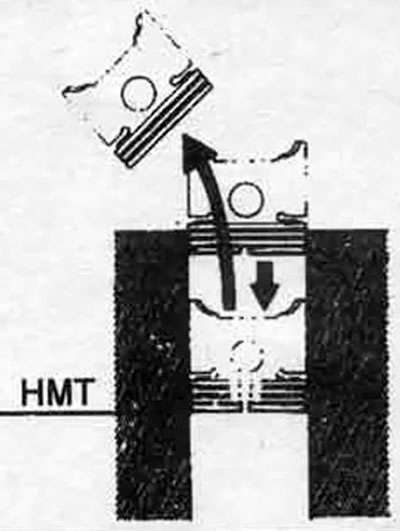
22.3. When checking the gap between the piston ring tips, install the ring without tilting it (this is achieved by pushing the ring into the cylinder with the piston head as shown)
4. To measure the gap between the ring tips, insert a flat feeler gauge of the appropriate size into the gap (see illustration). The feeler gauge should pass through the gap with slight resistance. Compare the measured value with the specification. If the gap is not within specification, repeat the measurement before continuing.
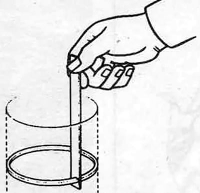
22.4. Having installed the ring in the cylinder without tilting, measure the end gap with a flat feeler gauge
5. If the gap is too small, it must be increased, otherwise the ring ends may abut each other when the engine is running, which will cause serious damage to the engine. The gap can be increased by filing down the ring ends with a fine file. Secure the file in a vice with soft jaws, place the ring on the file so that the ring ends touch the file, and slowly move the ring, filing down the material. When performing this operation, file down the material only from the outside in (see illustration).
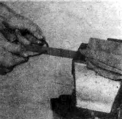
22.5 If the gap between the tips is too small, clamp a file in a vice and file the tips (from the outside in only) to increase the gap
(The original article is on: mitsubishiman.ru)
6. The increased gap does not matter much unless it is more than 1 mm. Repeat the measurement to make sure that you have indeed installed the correct ring.
7. Repeat the procedure for all rings that will be installed in the first cylinder and for all other rings that will be installed in the other cylinders. Do not mix up the matched rings, pistons and cylinders.
8. After checking/adjusting the end clearances, the rings can be installed on the pistons.
9. The oil control ring (the bottom one on the piston) is usually installed first. It consists of three separate pieces. Install the spacer/expander into the groove (see illustration). If a locking tab is used, insert it into the hole drilled in the groove. Then install the lower scraper. Do not use a piston ring installer when installing the oil control ring scrapers to avoid damaging them. Instead, insert one end of a side scraper into the groove between the spacer/expander and the groove guide and, holding it in place, run your finger around the piston, pushing the scraper into the groove (see illustration). Then install the upper scraper in the same way.
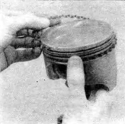
22.9a. Installing a spacer/expander into the groove of the oil scraper ring
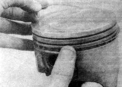
22.9b. When installing the side scrapers of the oil scraper ring, do not use a ring installer
10. After installing the three oil scraper ring elements, ensure that both the upper and lower scrapers can rotate freely in the groove.
11. The second (middle) ring is installed next. It usually has a stamped mark that should be facing upwards towards the piston bottom (see illustration).
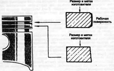
22.11. Compression rings No.1 (upper) and No.2 have different cross-sections - install them in the correct places with the marks facing up
Note: On 1.8L Turbo and 2.0L (Cordia/Tredia only) engines, the ring thickness varies depending on the engine. The dimensions are shown in the table.
| Number | Engine | Ring thickness | Identification tag |
| №1 | 1.8L | 1.5 mm | т |
| 2.0L | 2.0 mm | N | |
| №2 | 1.8L | 1.5 mm | 2Т |
| 2.0L | 2.0 mm | N |
Note: Always follow the instructions printed on the piston ring packaging - different manufacturers may have different requirements. Do not confuse the top and middle rings, as they have different cross-sections.
12. Using a piston ring installer and making sure the identification mark is facing the top of the piston, insert the ring into the center groove of the piston (see illustration). Do not spread the ring more than necessary to install it on the piston.
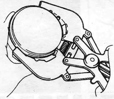
22.12. Install the compression ring using the tool - the mark (arrow) should be on top
13. Install the first (upper) ring in the same way. Make sure that the marking is facing up. Do not confuse the first ring with the second.
14. Repeat the procedure with the remaining pistons and rings.