



Contents: Piston ring ⤓ Connecting rod bearing radial…⤓
Piston ring
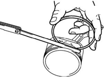
1. Check the piston ring axial clearance. If it exceeds the maximum allowable value, replace the piston ring, piston, or both (See the picture).
Standard value (model with 6V31 engine):
- First ring: 0.04-0.08 mm.
- Second ring: 0.03-0.07 mm.
Maximum allowable value: 0.1 mm.
Standard value (model with 6G7 engine):
- First ring: 0.03-0.07 mm.
- Second ring: 0.02-0.06 mm.
Maximum allowable value: 0.1 mm.
Standard value (model with 4M4 engine):
- First ring: 0.06-0.08 mm.
- Second ring: 0.05-0.07 mm.
Maximum allowable value: 0.1 mm.
The original article is on: mitsubishiman
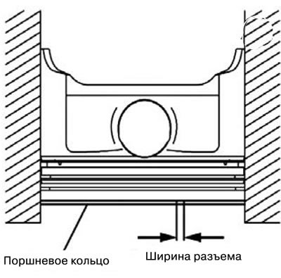
2. Insert the piston with piston rings into the cylinder so that the plane of the piston ring is located perpendicular to the longitudinal axis of the cylinder. Then measure the width of the ring joints. If it exceeds the maximum permissible value, replace the piston ring with a new part (See the picture).
Standard value (model with 6V31 engine):
- First ring: 0.18-0.33 mm.
- Second ring: 0.28-0.48 mm.
Oil deflector ring: 0.10-0.60 mm.
Maximum allowed value:
- First ring: 0.8 mm.
- Second ring: 0.8 mm.
Oil deflector ring: 1.0 mm.
Standard value (model with 6G7 engine):
- First ring: 0.20-0.40 mm.
- Second ring: 0.35-0.50 mm.
Oil retaining ring: 0.10-0.35 mm.
Maximum allowed value:
First ring: 0.8 mm.
Second ring: 0.8 mm.
Oil retaining ring: 1.0 mm.
Standard value (model with 4M4 engine):
First ring: 0.20-0.30 mm.
Second ring: 0.20-0.30 mm.
Oil retaining ring: 0.30-0.50 mm.
Maximum allowed value:
- First ring: 0.8 mm.
- Second ring: 0.8 mm.
Oil retaining ring: 1.0 mm.
Connecting rod bearing radial clearance
1. Clean the connecting rod and connecting rod bearing from engine oil.
2. Place a plastic template on the crank, the length of which corresponds to the width of the connecting rod bearing, positioning it parallel to the longitudinal axis of the crank.
3. Carefully install the connecting rod big end cap into the mounting position and tighten the bolts to the tightening torque specified in the specification.
4. Unscrew the bolts and carefully remove the large connecting rod head cover.
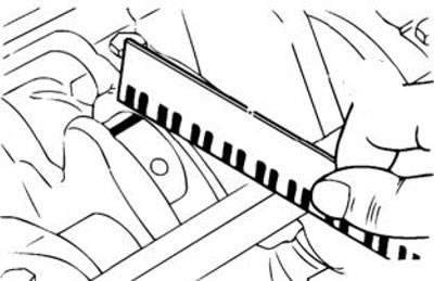
5. Measure the protruding part of the plastic template at its widest point by pressing a ruler against the plastic template as shown in the figure.
Model with 6V31 engine:
- Standard value: 0.012-0.039 mm.
- Maximum allowable value: 0.1 mm.
Other models:
- Standard value: 0.028-0.046 mm.
- Maximum allowable value: 0.1 mm.