



Radial clearance of crankshaft journal
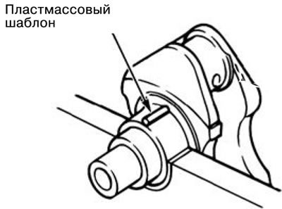
The radial clearance of the crankshaft journal can be conveniently measured using a plastic template.
Measurement procedure:
- 1. Clean the bearing and crankshaft journal from engine oil.
- 2. Insert the crankshaft into the bearing.
- 3. Place a plastic template on the shaft journal, the length of which corresponds to the width of the crankshaft bearing, positioning it parallel to the longitudinal axis of the crankshaft (See the picture).
4. Carefully install the crankshaft cover into the mounting position and tighten the bolts to the tightening torque specified in the specification.
5. Unscrew the bolts and carefully remove the crankshaft cover.
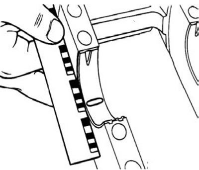
6. Measure the protruding part of the plastic template at its widest point by pressing a ruler against the plastic template as shown in the figure.
Default value:
- no. 1, No. 4: 0.012-0.03 mm.
- no. 2, No. 3: 0.018 0 0.036 mm.
Maximum allowable value: 0.1 mm.
Note: The crankshaft journal and crankshaft pin are crimped. Processing of the specified parts to reduce their size is not permitted.
Cylinder block
1. Check the cylinder block for cracks, corrosion or rust by visual inspection and using a flaw detector. Eliminate defects or replace the cylinder block with a new part.
2. Clean the surface of the cylinder block from stuck pieces of gasket and other foreign objects. Measure the flatness of the top surface of the cylinder block (See the picture).
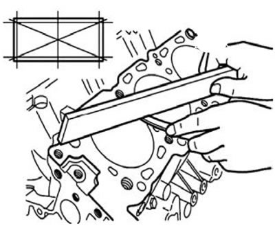
Standard value: < 0.05mm. Maximum allowable value: 0.1mm.
3. Check the inner surface of the cylinders for cracks or burrs. If any noticeable defects are detected, treat the cylinder block to an increased repair size or replace it with a new part.
4. Measure the dimensions and cylindricity of each cylinder.
If even one of the cylinders is significantly worn, treat all cylinders to an increased repair size and install new pistons and rings of the appropriate size (See the picture).
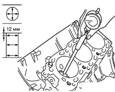
Standard value (model with 6G7 engine):
- Cylinder diameter: 95.0 mm.
- Cylindricity deviation tolerance: < 0.01mm.
Standard value (model with 4M4 engine):
- Cylinder diameter: 98.5 mm.
- Cylindricity deviation tolerance: < 0.015mm.
Oversized cylinder
1. Select pistons of increased repair size according to the maximum cylinder size.
2. Options for increasing the cylinder size: 0.25 mm, 0.50 mm.
The clearance between the piston and the oversized cylinder must correspond to the range of acceptable values.
Measure the piston diameter in the position shown in the figure.
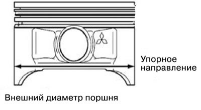
3. calculated diameter of the cylinder of increased repair size.
Calculated diameter = piston diameter + allowable clearance (0.02-0.04 mm) - 0.02 mm.
4. Boring the cylinder to the calculated diameter.
5. Grind the cylinder to the final diameter (piston diameter + standard clearance).
6. Check the clearance between the piston and the cylinder.
Standard value (model with 6G7 engine): 0.02-0.04 mm.
Standard value (model with 4M4 engine): 0.04-0.05 mm.
Note: The cylinder boring sequence is: second, fourth, sixth, first, third, fifth cylinders.
Cylinder honing
Use cylinder honing only if the cylinder bore is scratched or rough.
1. Measure the diameters of the engine cylinder bores. If necessary, bore the cylinder block to the repair size and measure the cylinder bore diameters again.
2. Hone the cylinder bore with honing oil and hone (abrasive 220). Use only hones with 220 grit or finer, such as Sunnen, Ammco or similar. Do not use hones that are worn or damaged.
3. After completing honing, thoroughly clean the cylinder block from all metal particles. Wash cylinder bores with hot soapy water, dry and immediately coat with motor oil to prevent rust. Do not use solvent as this will only redistribute the abrasive particles over the cylinder surface.
4. If scratches and roughness are still present after honing the cylinder to the maximum allowable size, rebore the cylinder block. Occasional shallow vertical scratches and roughness are acceptable, provided they are not deep enough to catch a fingernail and do not continue the entire length of the cylinder.