



Contents: Display of valve timing marks on a…⤓ Removal the timing belt ⤓ Sequence of unscrewing cylinder head…⤓ Lower body ⤓
Display of valve timing marks on a diesel engine
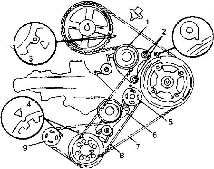
1. Timing belt tension roller; 2. Mounting bolts; 3. Mark on the camshaft; 4. Mark on the toothed pulley of the compensation shaft; 5. Toothed pulley of the compensation shaft; 6. Tensioner of the drive belt of the compensating shaft; 7. Timing belt of the gas distribution shaft drive; 8. Timing belt of the compensation shaft; 9. Compensating shaft drive pulley
Removal the timing belt
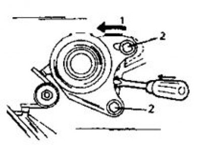
Place the tension roller in the direction of the arrow.
1. Water pump
2. Nut
Sequence of unscrewing cylinder head bolts
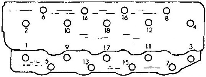
Tightening of the bolts is carried out in the reverse order.
Lower body
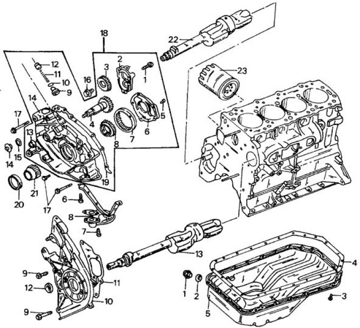
1. Oil drain plug; 2. Gasket; 3. Oil pan bolts; 4. Oil pan gasket; 5. Oil pan; 6. Bolt; 7. Bolt; 8. Oil intake tube mesh; 9. Front housing bolts; 10. Front upper body; 11. Housing gasket; 12. Seal; 13. Left compensation shaft; 14. Threaded plug; 15. O-ring seal; 16. Fastening bolts; 17. Fastening bolts; 18. Front lower body; 19. Lower housing casing; 20. Front oil seal; 21. Oil pump gear shaft; 22. Right compensation shaft; 23. Oil filter
Front lower body parts (18): 1. Mounting bolts; 2. Compensating shaft belt pulley cover; 3. Compensating shaft belt pulley; 4. Drive gear; 5. Bolt; 6. Oil pump cover; 7. External gear of oil pump; 8. Internal gear of oil pump; 9. Safety valve plug; 10. Gasket; 11. Safety valve spring; 12. Oil relief valve; 13. Seal; 14. Front lower body
Attention! The sequence of engine disassembly as part of a major overhaul is given.
1. Drain the oil from the engine.
2. Remove all attachments from the engine. If you have any doubts about how to perform a particular task, please consult the relevant section of the book.
3. Remove the clutch. To do this, lock the flywheel accordingly.
Use a punch to mark the flywheel and clutch to ensure that the parts are installed in the same position when reinstalled. Loosen the clutch bolts evenly around the circumference before finally removing them.
4. Loosen the alternator mounting bolts and remove the drive V-belt. After this, remove the generator. Also unscrew the belt tensioner from the cylinder block.
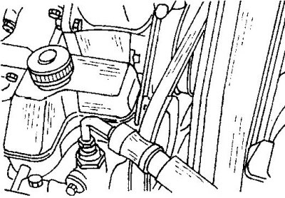
5. Remove the power steering pump drive belt. To do this, unscrew the bolt shown in the figure and the adjusting rod bolt and remove the belt.
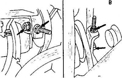
6. Remove the air conditioning compressor drive belt (B - on diesel engines).
To do this, loosen the tension roller nuts enough to allow the drive belt to be removed. Unscrew the belt pulley mount included.
7. Remove the radiator fan and viscous coupling from the front of the engine, as well as the water pump belt pulley.
8. Remove the upper half of the timing cover together with the gasket.
9. Remove the two cylinder head cover bolts and remove the gasket and semi-circular seal from the cover or from the cylinder head.
10. While holding the crankshaft from turning, loosen the crankshaft belt pulley bolt. Remove the belt pulley. To do this, place two crowbars on opposite sides under the belt pulley. Be careful not to damage the parts.
11. Unscrew the lower half of the timing cover and remove the gaskets from the left and right sides.
12. Turn the engine until the piston of the first cylinder is in the top dead center position. To check the correct installation of the crankshaft, take both rocker arms of the first cylinder with your thumb and index finger and rock them in different directions. If both rocker arms have clearances, then the crankshaft is aligned correctly. In this case, the marks on the engine occupy the position shown in the figure Exhibition of valve timing marks on a diesel engine.
13. Mark the direction of rotation with chalk on the back of the timing belt and also the idler shaft drive belt if the belts are to be reinstalled.
14. Loosen both bolts and use a screwdriver to push the timing belt tension roller toward the water pump (see picture Removing the timing belt). Once the belt is loose, tighten the nut so that the tension roller cannot return to its original position.
15. Remove the timing belt and drive belt from the timing pulleys. After this, the engine cannot be turned until the cylinder head is unscrewed. Store both belts in a protected location to prevent them from being exposed to oil or grease. Do not bend the straps.
16. Remove the rocker arm shaft from the cylinder head.
17. Unscrew the camshaft bearing caps and remove the camshaft from the cylinder head. The bearing caps sit on centering pins. A firmly stuck lid can be moved by lightly tapping it with a rubber mallet. If necessary, remove the camshaft timing pulley.
18. Loosen the cylinder head bolts in several passes in the sequence shown in the figure Sequence of unscrewing the cylinder head bolts. A special wrench head is used to loosen the bolts. If necessary, pry the cylinder head loose with a plastic or rubber mallet. Never insert a screwdriver between the cylinder head and the cylinder block to pry the head away from the block.
19. Remove and discard the cylinder head gasket, regardless of the appearance of the gasket. Immediately clean the cylinder head surface from any remaining sealant.
20. Unscrew the oil pan.
21. Remove the front housing, cardan shafts and oil pump as follows.
22. Unscrew the front upper housing and remove the gasket. Immediately press out the seal from the rear side of the upper housing. Remove the left compensation shaft.
23. Unscrew the plug from the front lower housing and insert a screwdriver with a rod diameter of 8 mm into the hole, thereby blocking the compensation shaft from turning.
24. Loosen the bolt securing the drive gear of the compensation shaft. If the shaft is in position, it is held from turning and the bolt is released. Press the belt pulley off the shaft using two pry bars on opposite sides.
25. Loosen the bolts and remove the lower housing. Seven bolts need to be removed.
26. Disassemble the lower case (see picture Lower body). This includes the oil pump, the compensating shaft pulley and both seals. Unscrew the filter screen of the oil intake pipe from the bottom of the engine crankcase. If both oil pump gears are removed, they should be marked with a punch before being removed to ensure that they are subsequently installed in their original position. The gaskets can be discarded immediately, as they are subject to replacement. To remove the oil pump drive gear, you can unscrew the cover of the compensating shaft belt pulley.
27. Using a special key, unscrew the oil filter from the side of the cylinder head.
If you don't have a special key, you can insert a screwdriver into the side of the oil filter and use it as a lever to unscrew the filter.
28. All other work is performed in the same way as on gasoline engines.
Pay attention to the position of the main bearing caps, as some have oil grooves while others do not.
29. Both outer bearing shells have lubrication grooves, but their position must be marked (in the engine crankcase or on the bearing shells).