



Correct assembly of the rocker shaft
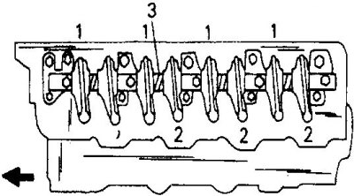
1. Intake valve rocker arms; 2. Exhaust valve rocker arms
Each of the springs (3) is located between the rocker arms.
Assembly drawing of diesel engine cylinder head
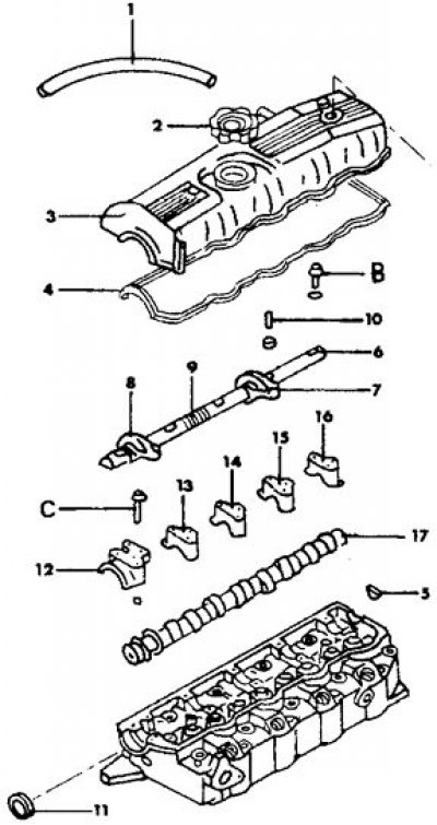
1. Ventilation hose; 2. Oil filler cap; 3. Cylinder head cover; 4. Cylinder head cover gasket; 5. Semi-circular seal; 6. Rocker shaft; 7. Intake valve rocker arm; 8. Exhaust valve rocker arm; 9. Rocker shaft spring; 10. Adjusting screw; 11. Camshaft oil seal; 12. Front bearing cap; 13. Bearing cover N₂; 14. Bearing cover N3; 15. Bearing cover N4; 16. Rear bearing cover; 17. Camshaft
The rocker arms for the intake and exhaust valves are different and are marked either "I" (intake valves), or "E" (exhaust valves). The oil injection holes on the rocker shaft should be positioned at the bottom after installation. The end of the shaft with one lubrication hole should be located at the front side. There are two lubrication holes at the other end of the shaft.
Bearing caps N₂, 3 and 4 are marked with their numbers. Bearing caps N1 and 5 are not marked as they can be distinguished by their shape.
Article reprinted from the website MitsubishiMan.ru
The rocker shaft is installed after the camshaft is installed.
1. Lubricate all rocker arm mechanism parts with engine oil and install the rocker arms and springs on the shaft.
2. Insert both bolts and spring washers and tighten the bolts to a torque of 35 to 40 N·m.
3. The remaining work is performed similarly to gasoline engines. Install the timing belt and other timing drive components. The figure Assembly drawing of the cylinder head of a diesel engine shows the details of the rocker shaft. After installation, adjust the valve clearances on a cold engine and bring them to the specified values after warming up the engine.