



Contents: Camshaft and high pressure fuel pump…⤓ Lower Timing Belt Drive Parts ⤓ Attaching the lower toothed belt…⤓ Installing a Timing Belt Tensioner ⤓ To the tension of the timing belt of…⤓ Installation ⤓
Camshaft and high pressure fuel pump drive parts
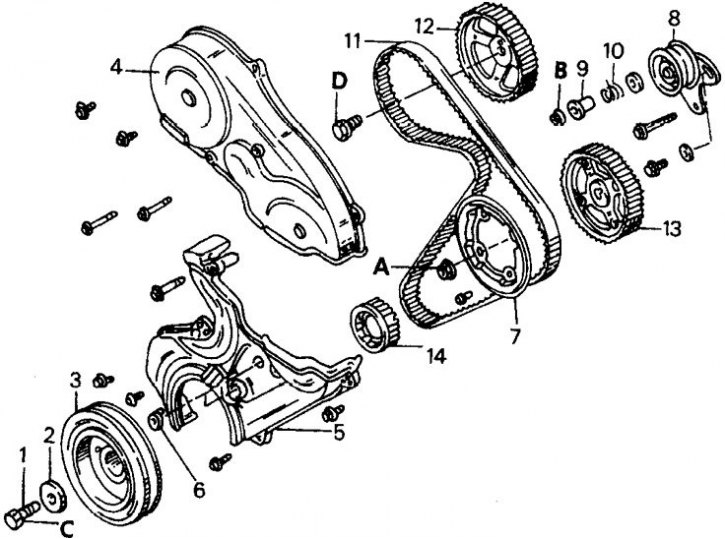
1. Crankshaft timing belt pulley bolt; 2. Special washer; 3. Crankshaft belt pulley; 4. Upper toothed belt guard; 5. Lower toothed belt guard; 6. Plug; 7. Flange; 8. Timing belt tension roller; 9. Spacer sleeve; 10. Timing belt tensioner spring; 11. Toothed belt; 12. Timing pulley of the camshaft; 13. High pressure fuel pump belt pulley; 14. Crankshaft toothed pulley; A = 80–90 Nm; B = 22–30 Nm; C = 170–190 Nm; D = 65–75 Nm
Lower Timing Belt Drive Parts
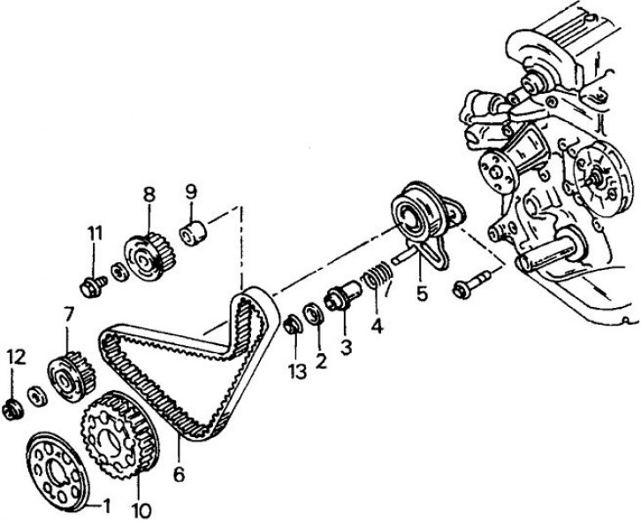
1. Flange; 2. Spacer washer; 3. Spacer sleeve; 4. Timing belt tensioner spring; 5. Timing belt tension roller; 6. Lower toothed belt; 7. Drive gear of the right compensation shaft; 8. Left compensation shaft drive gear; 9. Spacer sleeve; 10. Crankshaft toothed pulley; 11. Bolt, 34-60 Nm; 12. Bolt, 34–40 Nm; 13. Nut, 22–30 Nm
Attaching the lower toothed belt (belt "B")
1. Mark on the compensation shaft; 2. Timing belt tension roller; 3. Marks on the toothed pulley of the crankshaft and on the compensation shaft; 4. Toothed belt "B"; 5. Crankshaft toothed pulley
Installing a Timing Belt Tensioner
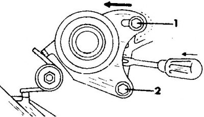
1, 2. Bolts
To the tension of the timing belt of the gas distribution mechanism drive
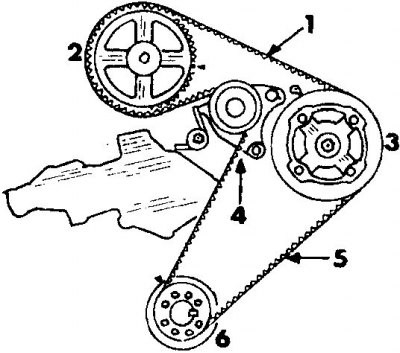
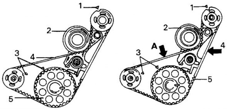
1. Belt tension side; 2. Timing pulley of the camshaft; 3. High pressure fuel pump drive gear; 4. Timing belt tension roller; 5. Belt tension side; 6. Crankshaft toothed pulley
The figures shown show a drive on an engine without compensation shafts.
In the following description, the timing belt for the camshaft drive will be referred to as the "B" belt. The description assumes that all timing drive components have been removed and must be installed.
Installation
1. Place the toothed pulley on the end of the crankshaft.
2. Install the spacer sleeve. The beveled side must face the compensation shaft. Incorrect installation may cause damage to the timing belt.
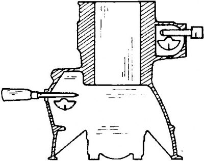
3. Place both drive gears on their respective shafts and tighten the bolt on one shaft and the nut on the other shaft to a tightening torque of 34–40 N·m. The shafts must be held from turning. To do this, unscrew the plug on the right side and insert a screwdriver, and unscrew the cover on the left side and insert a metal rod.
4. Install the timing belt tension roller "B", tensioner spring and spacer sleeve. Place the washer and hand tighten the nut.
5. Apply toothed belt "B" (see figure Applying the lower toothed belt (belt "B")). Align the marks on the crankshaft toothed pulley with the marks on both drive gears of the compensation shafts. Apply the toothed belt, making sure to tension the right side of the belt. When reinstalling a removed timing belt, it must be placed in its original position.
6. Press your finger on the toothed belt at location "A" and check again that the marks match. If the marks are out of alignment, remove the belt again and turn the corresponding pulley one tooth to the right or left.
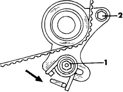
7. Loosen the timing belt tensioner roller nut one or two turns to allow the timing belt tensioner spring to press the tensioner roller against the timing belt. Press the tension roller in the direction indicated by the arrow. After this, first tighten the nut (1) and then the bolt (2).
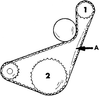
8. Check the tension of the toothed belt by pressing the belt with your finger at point "A" between belt pulleys 1 and 2. The belt deflection should be between 4 and 5 mm. If necessary, loosen the nut and bolt and press the tension roller against the toothed belt again.
9. Install the crankshaft timing pulley, high pressure fuel pump drive gear and camshaft timing pulley. Tighten the bolts to the specified tightening torques. While doing this, hold the shafts from turning.
10. Install the timing belt tensioner roller. Install the tension roller with the spring and spacer sleeve and screw on the nut. Press the tension roller with a screwdriver in the direction of the arrow (see figure Installing the timing belt tensioner) and in this position tighten the bolt. Tighten the bolt by hand.
11. Turn the toothed pulleys so that the marks are positioned as shown in the figure Align the timing marks on a diesel engine and apply the toothed belt without turning the toothed pulleys. Ensure belt tension in the locations shown in the figure To the timing belt tensioner, and apply the belt in the following sequence: crankshaft toothed pulley, high-pressure fuel pump drive gear, tension roller and camshaft toothed pulley.
12. When applying the timing belt to the high pressure fuel pump gear, it should be held as it can easily turn. When reinstalling a removed timing belt, it should be installed in its original position. Check the position of the marks after applying the timing belt.
13. Loosen bolt "1" (see figure Installing the timing belt tensioner) one or two turns and allow the tension roller to press against the toothed belt, that is, in the direction of the arrow in the figure. Check the position of the marks again. Turn the crankshaft two teeth of the pinion shaft and leave it in this position. In this case, turn the crankshaft in the direction of engine rotation and in no case the other way around. In this position, first tighten bolt "2" and then bolt "1" to a tightening torque of 22–30 N·m.
14. Turn the crankshaft back again until the marks match and check the tension of the toothed belt between the toothed pulley of the camshaft and the drive gear of the high-pressure fuel pump. When pressing the belt with your finger, the belt deflection should be 4-5 mm. If necessary, readjust the toothed belt tension.
15. Install the flange. Please note that the flange and drive gear holes are offset, meaning the flange can only be installed in one position.
Insert and tighten the bolts.
16. While holding the high pressure fuel pump drive gear, tighten the nut to a tightening torque of 80–90 N·m.
17. The remaining work is performed in reverse order. Tighten the crankshaft belt pulley bolt to 170–190 N·m. While doing this, hold the crankshaft from turning. If the engine is installed, engage the gear. Otherwise, lock the flywheel ring gear.