



Contents: SOHC Engines Removal ⤓ Examination ⤓ Installation ⤓ DOHC engines ⤓ Removal ⤓ Examination ⤓ Installation ⤓
Caution! Do not attempt to rotate the crankshaft using the bolt located on the crankshaft sprocket, do not rotate the crankshaft counterclockwise, and do not rotate the crankshaft after you have removed the timing belt.
1. Set piston N1 to top dead center.
2. Disconnect the wire from the negative terminal of the battery.
3. Remove the air filter and related hoses.
4. Set the handbrake and block the rear wheels. Jack up the front of the car and secure it on supports installed under the axles.
5. Remove the left engine mount.
Attention! The engine must rest on a stand installed under the oil pan.
SOHC Engines Removal
6. Loosen the water pump pulley bolts and remove the drive belts.
7. Unscrew and remove the water pump pulley.
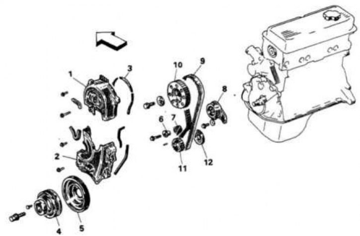
7.8a Timing belt for 1.5L engine
1. Top cover; 2. Bottom cover; 3. Gasket; 4. Damper pulley; 5. Crankshaft pulley; 6. Tensioner bushing; 7. Tensioner spring; 8. Tensioner; 9. Timing belt; 10. Camshaft sprocket; 11. Crankshaft sprocket; 12. Belt guide
8. Unscrew the bolts securing the upper timing belt cover (7.8a, 7.8b, 7.8c, 7.8g, 7.8d) and remove the cover. Unscrew the bolts securing the lower cover and remove it.
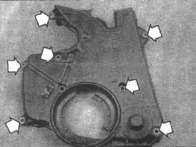
7.8d Arrows indicate the location of the lower timing belt cover bolts (2.0L)
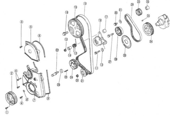
7.8b Timing belt for 1.8L, 2.0L, 2.4L engines
1. Bolt; 2. Crankshaft pulley; 3. Flange bolt; 4. Flange bolt; 5. Upper front cover; 6. Gasket; 7. Access hole cover; 8. Gasket; 9. Gasket; 10. Timing belt; 11. Flange bolt; 12. Washer; 13. Nut; 14. Bushing; 15. Tensioner spring; 16. Tensioner; 17. Bushing; 18. Bolt; 19. Camshaft sprocket; 20. Nut; 21. Oil pump sprocket; 22. Crankshaft sprocket bolt; 23. Washer; 24. Crankshaft sprocket; 25. Spring pin; 26. Flange; 27. Bolt; 28. Rear part of the tensioner; 29. Silent Shaft Belt; 30. Flange bolt; 31. Washer; 32. Silent shaft sprocket; 33. Bushing; 34. Rear crankshaft sprocket; 35. Key
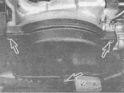
7.8v The upper timing belt cover is secured with three bolts (indicated by arrows) (2.0 l)
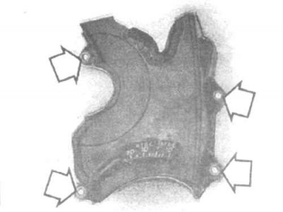
7.8g Arrows indicate the location of the lower timing belt cover bolts (1.5 l)
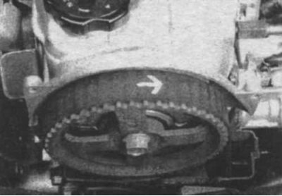
7.9 If you are going to reuse the timing belt, draw an arrow on it indicating the direction of rotation (clockwise)
9. If you are going to reuse the timing belt, draw an arrow on it indicating the direction of rotation (clockwise) (7.9).
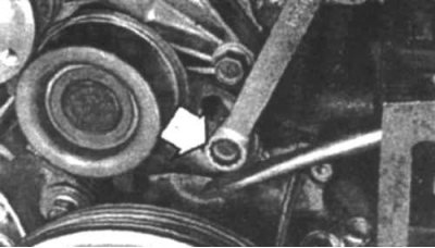
7.10a Loosen the tensioner bolt (indicated by the arrow) and move the tensioner towards the water pump (1.5 l)
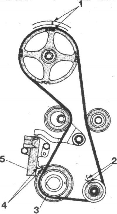
7.10v Timing mark locations on 16-valve SOHC engines. The automatic tensioner is secured with two bolts, the tensioner plunger presses on the tensioner lever, which in turn presses the tensioner pulley against the belt
1. Timing marks of the camshaft sprocket; 2. Timing marks of the oil pump sprocket; 3. Crankshaft sprocket; 4. Crankshaft sprocket timing marks; 5. Automatic tensioner
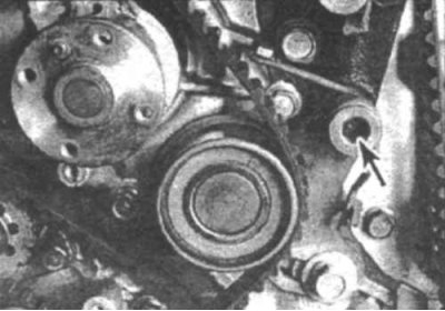
7.10b Tensioner bolt (indicated by arrow) (2.0 l)
10. In 8-cylinder engines, loosen the adjusting bolt and move the timing belt tensioner towards the water pump until it stops (7.10a, 7.10b, 7.10c). Temporarily secure the tensioner in this position by tightening the bolt. In 16-valve engines, unscrew and remove the tensioner, loosen the tensioner lever bolt so that the lever hangs freely (7.10c).
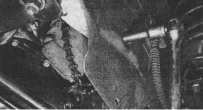
7.11 Unscrew the central bolt of the crankshaft pulley (1.5 l)
11. Remove the large center bolt from the crankshaft pulley (7.11).
Please note: On some models the pulley is secured with four bolts.
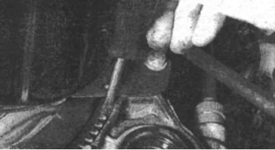
7.12 Insert a screwdriver between the flywheel teeth to prevent the crankshaft from rotating.
12. If you cannot unscrew the bolt because your key is slipping, lock the crankshaft by inserting a screwdriver between the teeth of the flywheel (7.12). In order to do this, you will first have to remove the flywheel cover.
13. Make sure the tensioner bolts are loose and remove the timing belt.
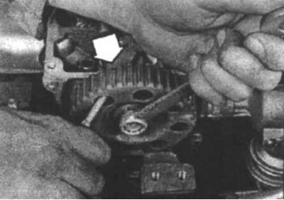
7.14 To prevent the sprocket from rotating while you unscrew the bolt, lock it by inserting a screwdriver into one of the holes. The tip of the screwdriver should rest against the gasket (indicated by the arrow) to avoid damaging the cylinder head (1.5 l)
14. If you want to remove the camshaft, unscrew the camshaft sprocket bolt and remove the sprocket. To prevent the sprocket from turning while you unscrew the bolt, lock it by inserting a screwdriver into one of the holes (7.14). Also remove the oil pump sprocket and check the pump seal for damage or leaks.
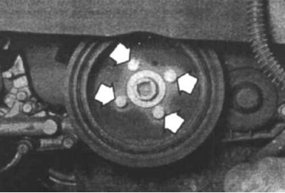
7.15a Remove the crankshaft pulley bolts (indicated by arrows) (2.0 l)
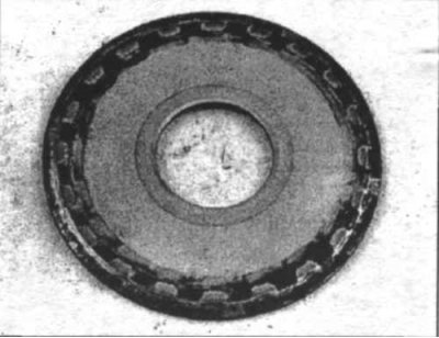
7.15b When removing the timing belt guide flange, remember its correct location (1.5 l)
15. If you want to replace the front crankshaft oil seal, unscrew the four crankshaft pulley bolts and remove the pulley (7.15a). Remove the crankshaft sprocket and the timing belt guide flange (7.15b) located behind the sprocket (remember the correct location of the flange).
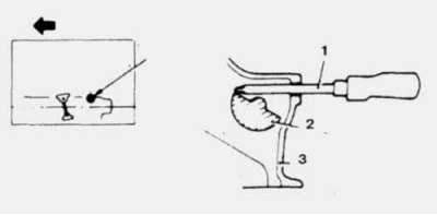
7.16 Use a screwdriver to lock the silent shaft
1. Screwdriver (8 mm); 2. Silent shaft; 3. Cylinder block
16. For 1.8L, 2.0L, 2.4L engines, remove the plug on the left side of the cylinder block and insert a screwdriver to lock the silent shaft (7.16).
17. Loosen the bolt securing the silent shaft sprocket.
18. Loosen the tensioner and remove the silent shaft belt (7.8v).
Examination
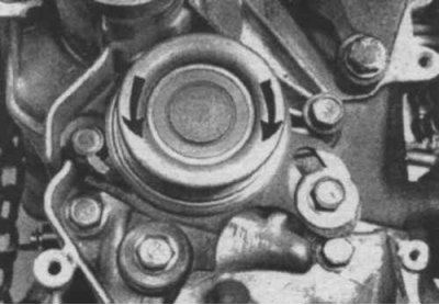
7.19 Rotate the tensioner pulley by hand and move it from side to side to check that the pulley is not sticking and that there is no excessive free play (1.5 l).
19. Rotate the tensioner pulley by hand and move it from side to side to check for binding or excessive free play (7.19). Inspect the sprockets for signs of wear or damage. Replace damaged parts if necessary.
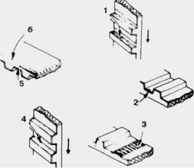
7.20 Carefully inspect the timing belt for damage
1. Rubber protrudes; 2. Detachment; 3. The tooth is missing and the fibers are protruding; 4. Wear on the working side; 5. Heavy wear; 6. Rounded side of the belt
20. Inspect the timing belt (7.20) for cracks, wear, delamination, missing teeth and oil contamination. Replace the belt if you doubt its suitability.
Installation
21. Install the timing belt sprockets if you removed them. Before installing the crankshaft sprocket, install the guide flange (7.8b, 7.8c, 7.8d).
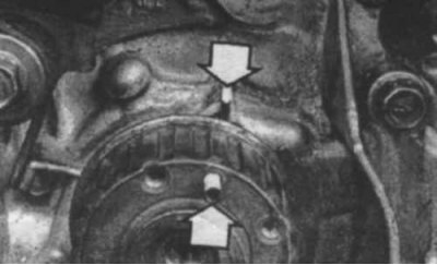
7.22a Align the pin on the crankshaft sprocket with the mark on the oil pump (indicated by arrows) (1.5 l).
22. Align the timing marks on the camshaft, crankshaft and oil pump sprockets with the marks on the cylinder head and cylinder block (7.22a, 7.22b, 7.22c, 7.10c).
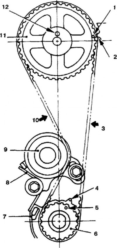
7.22v Timing marks on the crankshaft and camshaft sprockets (1.5 l).
1. Timing mark (camshaft sprocket); 2. Timing mark (cylinder head); 3. The tensioned side of the belt; 4. Timing mark (cylinder block); 5. Timing mark (crankshaft sprocket); 6. Crankshaft sprocket 7. Cylinder block; 8. Tensioner spring; 9. Belt tensioner; 10. Weak side of the belt; 11. Camshaft sprocket; 12. Pin
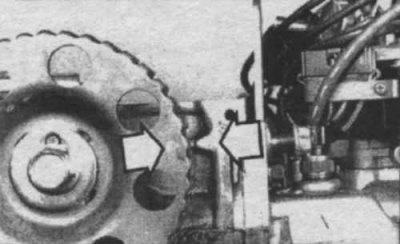
7.22b Align the triangular mark on the camshaft sprocket with the mark on the cylinder head (indicated by arrows) (1.5 l).
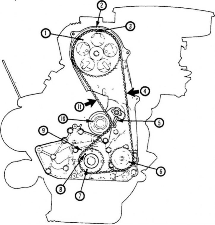
7.22g Synchronization marks on the crankshaft and camshaft sprockets (1.6L engine).
1. Camshaft sprocket; 2. Timing mark on the timing belt cover; 3. Synchronization mark; 4. The tensioned side of the belt; 5. Tensioner spring; 6. Oil pump sprocket; 7. Crankshaft sprocket; 8. Synchronization mark; 9. Synchronization mark on the cylinder block; 10. Belt tensioner; 11. Weak side of the belt
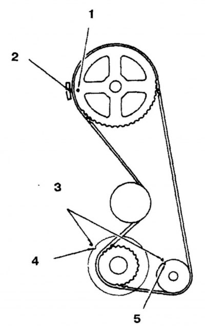
7.22d Synchronization marks on the crankshaft and camshaft sprockets (1.8 l, 2.0 l, 2.4 l engine).
1. Synchronization mark (hole in the sprocket); 2. Timing mark (on the cylinder head); 3. Timing marks (on the cylinder block) 4. Timing mark (slot in the flange); 5. Synchronization mark (slot in the sprocket)
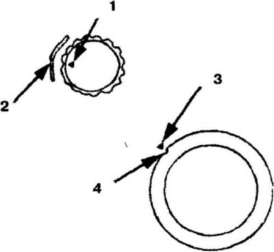
7.23 Before installing the rear belt, align the timing marks (1.8L, 2.0L, 2.4L engines)
1. Synchronization mark (on the sprocket); 2. Synchronization mark (slot in the cylinder block); 3. Timing mark (on the cylinder block); 4. Synchronization mark (slot in the sprocket)
23. For 1.8L, 2.0L, 2.4L engines, install the rear belt. Align the timing marks on each sprocket with the marks on the cylinder block (7.23)
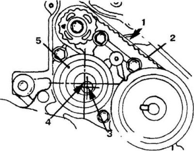
7.24 Installing the timing belt.
1. The tension side of the belt; 2. Back belt; 3. Central belt; 4. Center of the tensioner pulley; 5. Rear belt tensioner
24. After you have installed the rear belt, make sure that the tensioned side of the belt does not sag (7.24).
25. Check that the center of the rear belt tensioner sprocket is located on the left side of the installation bolt (7.24).
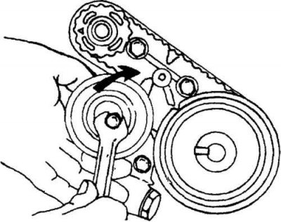
7.25a Turn the tensioner clockwise and upward to tighten the belt
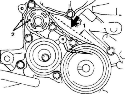
7.25b Press the middle of the belt to check its deflection
1. Synchronization marks; 2. Synchronization marks
Lift the tensioner with your finger to tighten the belt (7.25a, 7.25b) and tighten the tensioner bolt and silent shaft bolt to the tightening torques specified in the specifications. The belt deflection should be in the range of 5.0-7.0 mm.
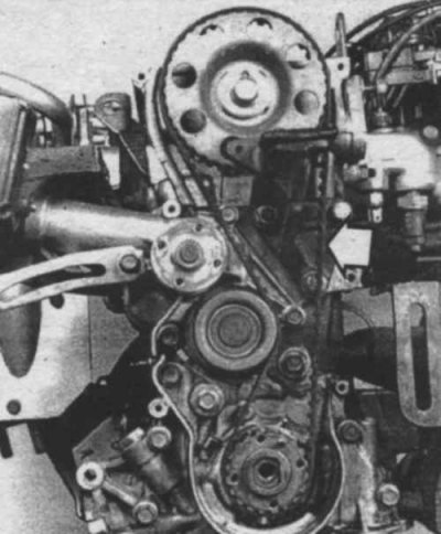
7.26 Installing the timing belt (1.5L)
26. Place the timing belt on the crankshaft sprocket. With the rear part of the belt tensioned, place it on the camshaft sprocket (7.26).
27. On 8-valve engines, loosen the tensioner lock bolt to tighten the belt. Tighten the bolt.
28. Install the crankshaft pulley by carefully aligning the dowel pin with the small hole in the pulley. Insert the pulley bolts (mounting bolts and center bolt) and tighten them to the specified torques.
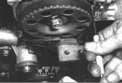
7.29 Alignment of timing marks on the camshaft sprocket
29. Turn the crankshaft two full revolutions. Check the alignment of the timing marks (7.29). If the marks are not aligned, loosen the tensioner, remove the belt from the camshaft sprocket, align the marks, install the belt in place and check the marks again.
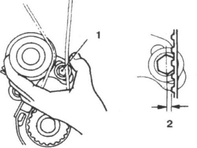
7.30a The belt is tensioned correctly if, when pressed, it deflects by one quarter of the width of the head of the adjusting bolt (1.5 L engines)
1. Tensioner bolt; 2. One quarter of the width of the bolt head
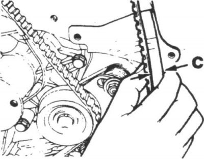
7.30b Press the belt against the cover and measure the distance between the belt and line C
30. On 1.5 litre engines, check the belt tension by pressing on it. The belt should deflect no more than one-quarter of the width of the adjusting bolt head (7.30a). If the belt is too tight or too loose, loosen the tensioner bolts and adjust the belt tension. On 1.8 litre, 2.0 litre (8-valve), 2.4 litre and 1.6 litre engines, press the belt against the cover (7.30b) and measure the distance between the belt and line C. The distance should be approximately 14 mm for 1.8 litre, 2.0 litre (8-valve) and 2.4 litre engines. On 1.6 litre engines the distance should be 6 mm.
31. Tighten the tensioner bolts to the required tightening torque.
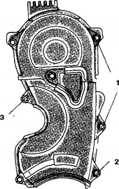
7.32 Insert the bolts into the timing belt cover (1.5L engines)
Thread diameter x Length (mm) 1.6x18 2.6x38 3.6x18
32. Install the remaining parts. Note that the timing belt cover bolts are of different lengths (7.32).
33. Start the engine and road test the vehicle.
DOHC engines
Attention! Mitsubishi DOHC 4G32 and 4G61 engines are the same, except that in the engine installed in the Colt, Lancer, Mirage (4G61 - 1989-1990) there is no silent shaft.
Removal
34. Perform the operations described in points 1-5.
35. Remove the power steering hose clamp and the air conditioning hose clamp.
36. Remove the drive belts and tensioner pulley bracket.
37 Remove the water pump pulley.
38. Remove the crankshaft pulley. Unscrew the bolts from the crankshaft pulley (7.11). If you cannot unscrew the bolt because the key is slipping, lock the crankshaft by inserting a screwdriver between the teeth of the flywheel (7.12).
39. Unscrew the mounting bolts of the upper and lower timing belt covers and remove the covers.
40. Remove the valve cover.
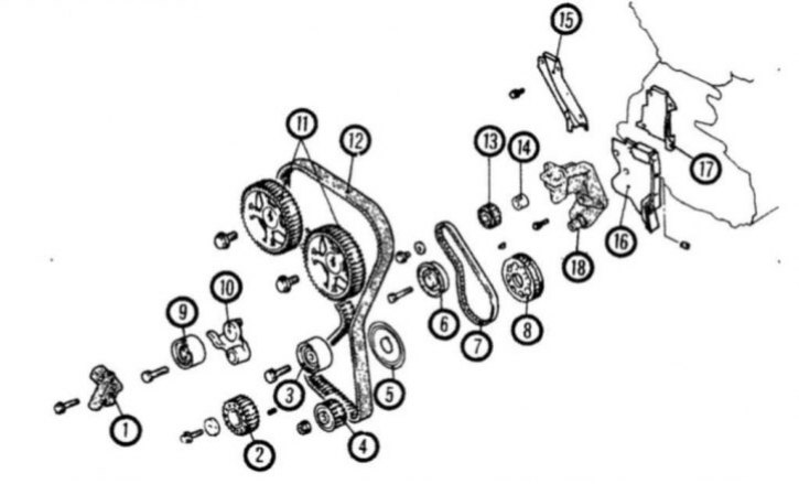
7.41 Timing Belts and Sprockets for DOHC Engines (4G32 engine shown)
1. Automatic tensioner; 2. Crankshaft sprocket; 3. Intermediate pulley; 4. Oil pump sprocket; 5. Flange; 6. Rear tensioner; 7. Rear belt; 8. Rear crankshaft sprocket; 9. Tensioner pulley; 10. Tensioner lever; 11. Camshaft sprocket; 12. Timing belt; 13. Silent shaft sprocket; 14. Bushing; 15. Rear right timing belt cover; 16. Rear left (lower) belt cover; 17. Rear left (upper) belt cover; 18. Engine support bracket
41. Remove the automatic tensioner (7.41).
42. If you are going to reuse the belt, make a mark on it indicating the direction of rotation (7.9). Remove the timing belt, tensioner arm and pulley (7.41).
43. Unscrew the bolts and remove the camshaft sprockets.
44 Remove the plug on the side of the cylinder block and lock the shaft by inserting a screwdriver into the hole. Unscrew the oil pump sprocket nut and remove the sprocket.
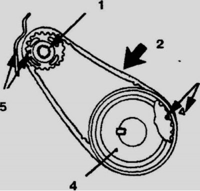
7.45 DOHC Engine Rear Timing Belt Marks
1. Silent shaft sprocket; 2. Tight side; 3. Synchronization mark; 4. Rear crankshaft sprocket; 5. Synchronization mark
45. On 4G32 DOHC engines, remove the rear timing belt. Before removing the belt, make sure the timing marks are aligned correctly (7.45).
Examination
46. Rotate the tensioner pulley by hand and move it from side to side to check for binding or excessive free play. Inspect the sprockets for wear or damage. Replace if necessary.
47. Inspect the timing belt (7.20) for cracks, delamination, wear, missing teeth and oil contamination. Replace belts if necessary.
48. Inspect the tensioner for leaks and obvious damage. Inspect the piston rod for wear and damage. Measure the piston rod protrusion, it should extend 12 mm from the tensioner body.
49. Clamp the tensioner in a vice. Check the condition of the rod. Replace the tensioner if necessary.
Installation
50. Reinstall the sprockets if you removed them. Tighten the bolts to the required torques.
Attention!
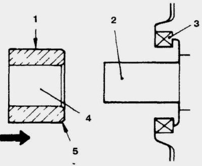
7.50 The cut edge of the bushing must be directed inwards
1. Grease with oil; 2. Right silent shaft; 3. Seal; 4. Bushing; 5. Cut edge
Make sure you install the sleeve correctly on the crankshaft sprocket (7.50).
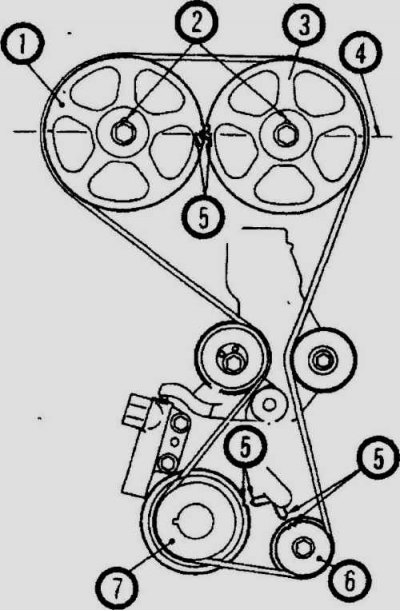
7.51 Make sure the timing marks are aligned correctly.
1. Exhaust camshaft sprocket; 2. Holes for mounting pins; 3. Intake camshaft sprocket; 4. Machined surface of cylinder head; 5. Synchronization marks; 6. Oil pump sprocket; 7. Crankshaft sprocket
51. Align the timing marks located on the camshaft, crankshaft and oil pump sprockets (7.51).
52. For 4G32 DOHC engines, install the timing belt. Install and adjust the rear belt, the belt deviation should be within 5.0-7.0 mm.
53. Prepare the automatic tensioner for installation. If the tensioner rod is completely protruding, clamp the tensioner in a vice and slowly push the rod in. Push the rod until the hole in it aligns with the hole in the tensioner body. Insert a piece of wire into the holes to lock the rod in this position.
54. Insert the automatic tensioner into place.
55. Install the tensioner pulley onto the arm. Finger tighten the center bolt, the two small holes in the pulley sleeve should be located on the left side of the center bolt.
56. Turn the two crankshaft sprockets so that the timing pins are located at the top (7.51). Align the timing marks with the top surface of the cylinder head.
57. Align the timing marks on the crankshaft and oil pump sprockets with the corresponding marks on the cylinder block (7.51).
58. Remove the plug on the side of the cylinder block and insert a long screwdriver (7.16) into the hole. If the screwdriver does not go deeper than 62 mm, this means that the marks are aligned correctly. If the screwdriver does not go deeper than 25 mm, then the oil pump sprocket needs to be adjusted.
59. Installing the timing belt:
- a. Pass the belt through the tensioner pulley and place it on the crankshaft sprocket.
- b. Place the belt on the oil pump sprocket.
- c. Place the belt on the idler pulley
- g. Place the belt on the intake camshaft sprocket.
- d. Turn the exhaust camshaft sprocket one tooth to align the timing mark on the sprocket with the mark on the top surface of the cylinder head (7.51). Place the belt on the exhaust camshaft sprocket.
- e. Carefully lift the tensioner pulley and temporarily tighten the center bolt.

7.60 Use the special tool to apply the required force to the tensioner
60. Adjust the timing belt tension:
- a. Turn the crankshaft one-quarter turn counterclockwise and then clockwise to set piston N1 to top dead center.
- b. Loosen the tensioner center bolt and connect the special tool NMD998752 (7.60) to the torque wrench.
- c. Tighten the center bolt to the specified torque.
- d. Screw the special tool NMD998738 into the left engine bracket until the tip of the tool touches the tensioner arm. Continue screwing the tool until the pressure on the automatic tensioner is relieved. Remove the wire that was inserted into the tensioner. Alternatively, you can press on the tensioner pulley to compress the tensioner rod, and then remove the wire.
- d. Unscrew the special tool.
- e. Turn the crankshaft two full revolutions and wait 15 minutes. Measure how long the tensioner rod protrudes. The required value is 3.8-4.5 mm.
61. If the protruding length of the rod is not within the required range, readjust the belt.
62. Install the belt covers.
63. Install the remaining parts in place.