



Removal
- Disconnect the cable from the negative battery terminal.
- Remove the lower engine splash shield.
- Remove the engine mount bracket.
- Loosen the bolt and remove the air conditioning hose clamp (Fig. 4.26).
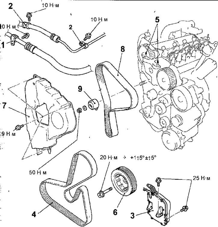
Fig.4.26. Timing drive toothed belt: 1 - Air conditioning hose mounting clamp; 2 - clamp for fastening the hydraulic power steering hose; 3 - Engine control unit (ECU); 4 - accessory drive belt; 5 - crankshaft pulley; 6 - hairpin; 7 - toothed belt cover; 8-toothed timing belt for gas distribution mechanism drive; 9 - toothed belt tensioner pulley
- Loosen the bolt and remove the clamp securing the power steering hydraulic hose.
- Remove the bolts and the engine control unit (ECU) along with the wires attached to it. Use a cord or soft wire to secure the removed ECU in the engine compartment so that it does not interfere with the removal of the timing belt.
- Loosen the bolt securing the pulley of the automatic tensioner mechanism of the accessory drive belt (see fig. 4.6).
- Using a 16 mm wrench placed on the lug on the automatic belt tensioner, turn it clockwise to loosen the tension and remove the accessory drive belt (see fig. 4.6).
Warning: Do not reuse a removed accessory drive belt.
- Turn the crankshaft clockwise until the timing mark on the camshaft pulley aligns with the center of the window in the timing belt housing (Fig. 4.27).
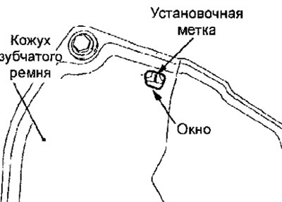
Fig. 4.27. Alignment of the timing mark on the camshaft pulley with the center of the window in the timing belt housing
- Using special tool MD998747, block the crankshaft pulley from turning and unscrew the pulley mounting bolt (see Fig. 4.7).
Warnings!
- 1. If you use the special tool MD998747 to lock the crankshaft pulley from turning with the belt installed on the engine, the belt will be damaged. Do not use the original engine accessory drive belt, but use a different belt.
- 2. Never reuse a damaged accessory drive belt.
Caution: When loosening the crankshaft pulley mounting bolt, do not turn the crankshaft or move the timing mark out of the window in the timing belt cover.
- Remove the pulley from the crankshaft.
- Loosen the nut securing the timing belt tensioner pulley and remove the belt (Fig. 4.28)
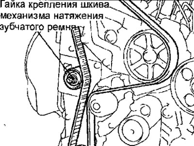
Fig. 4.28. Location of the nut securing the timing belt tensioner pulley
Warnings.
- If you are reusing the timing belt, use chalk to mark an arrow on the reverse (non-working) side of the belt surface indicating the direction of rotation of the belt (clockwise).
- Apply marks to the camshaft and crankshaft pulleys, as well as to the back of the timing belt, to determine the relative position of the pulleys.
Examination
- See the corresponding description in the section "Petrol engines 4G93".
Installation
- Installation is carried out in the reverse order of removal, taking into account the following.
- Rotate the crankshaft clockwise and set it to a position where the crankshaft groove is centered between the two ribs on the front crankshaft cover (Fig. 4.29). Also, make sure that the crankshaft pulley timing mark is offset to the left by one tooth from the vertical line passing through the center of the crankshaft.
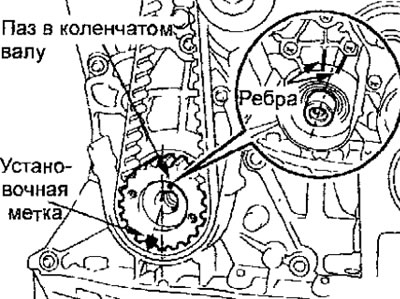
Fig. 4.29. Initial position of the crankshaft before installing the timing belt
- Make sure that the timing mark on the camshaft pulley is aligned with the center of the window in the timing belt cover (see Fig. 4.27).
- Install the timing belt so that the previously applied marks on the crankshaft and camshaft pulleys and on the reverse side of the timing belt are aligned (Fig. 4.30).
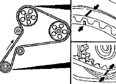
Fig. 4.30. Alignment of marks on the crankshaft and camshaft pulleys and on the reverse side of the timing belt
- Place the microphone (MB991668) connected to the MUT-II device perpendicular to the belt surface (at an angle of ±15°) at a distance of approximately 10-20 mm from the rear surface of the belt (Fig. 4.31). Rotate the M6 bolt to adjust the tension of the timing belt and check that the belt oscillation frequency corresponds to the nominal value (Fig. 4.32).
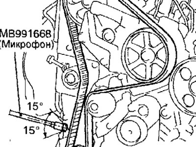
Fig. 4.31. Location of the microphone when checking the tension of the timing belt
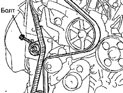
Fig. 4.32. Location of the timing belt tension adjustment bolt
[The original was published on the website MITSUBISHIMAN.ru]
Timing belt oscillation frequency: 90+15 Hz
- Using special tool MD998747, lock the crankshaft pulley from turning and tighten the crankshaft pulley mounting bolt to a torque of 20 N·m, then turn it further to an angle of 115°+15° (see fig. 4.8).
- Install and adjust the tension of the accessory drive belt.
- Install the Engine Control Unit (ECU).
- Install the air conditioning and power steering hose clamps and secure them with bolts.
- Install the engine mount bracket.
- Install the lower right engine splash shield.
- Connect the wire to the negative terminal of the battery.