
- Checking and adjusting valve clearances must be carried out on a cold engine.
- Remove the cylinder head cover.
- Check and adjust the clearances in the valve drive in the following sequence. Identify cylinder with equally open intake and exhaust valves and check valve clearances on cylinder with closed intake and exhaust valves (pic. 4.1).
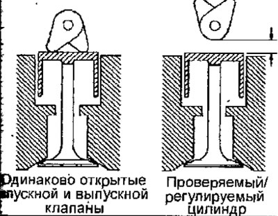
Pic. 4.1. The position of the camshaft cams with closed and open valves of one cylinder
- At the crankshaft pulley bolt, sequentially rotate the engine crankshaft a quarter of a turn and take the following measurements.
- Using a metal feeler gauge, measure the clearance in the valve actuator (pic. 4.2). When measuring the gap, the feeler blade must move very tightly.
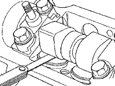
Pic. 4.2. Using a metal feeler gauge to measure valve clearance
Rated clearance (engine cold):
- when checking:
- inlet valve: 0.15-0.20mm
- - exhaust valve: 0.35-0.45 mm
- when adjusting:
- inlet valve: 0.20mm
- exhaust valve: 0.40mm
- If the valve clearance is outside the nominal value, adjust it by selecting the tappets of the required thickness, performing the following operations.
- Re-measure out-of-spec valve clearances and record the actual valve clearance.
- Measure the distance with a micrometer (pic. 4.3) from the end of the central pin to the front surface of the pusher.
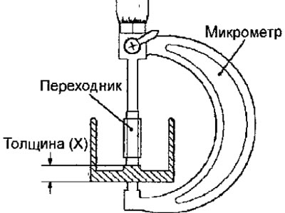
Pic. 4.3. Using a micrometer to measure push rod thickness
- Calculate the thickness of the new pusher as follows:
- Pusher thickness for adjustment = thickness of the removed pusher (X) + (measured value - nominal gap value)
- Select a pusher that is the correct thickness for the required value. If a pusher of the required thickness is not available, take a pusher with a thickness closest to the design value.
Note
(1) Measure the thickness of the pusher only with a micrometer.
(2) Always use only new tappets.
(3) The pushers have a thickness of 7.550 mm to 8.150 mm in 0.025 mm increments.
- Remove the camshaft and install the selected pushrod.
- Clean and degrease the mating surfaces of the cylinder head and camshaft bearing caps. Use an appropriate solvent for cleaning, and it is very important not to scratch the aluminum alloy of which the cylinder head is made.
- Lubricate and install the camshaft.
- Using a paint roller, apply Loctite 518 to the mating surface of the camshaft bearing cap until it becomes «reddish» and remove excess paste that has fallen on the bearings.
- Install the cover of the camshaft bearings and screw in the bolts for fastening the cover and the inner casing of the timing belt, having previously applied a blocking compound to the threads of the bolts (e.g. Loctite Frenfitanch).
- Tighten the camshaft bearing cover bolts in sequence.
- Install the cylinder head cover with a new gasket and tighten the cover bolts in sequence.
- Install the vacuum pump with a new gasket.
- Rotate the camshaft one turn and check that the valve clearances are within specification.
- Install the cylinder head cover.