



Contents: Removal ⤓ Installation ⤓
Removal
To remove, follow these steps in sequence.
1. Disconnect the cable from the negative terminal of the battery.
2. Remove the engine protective cover.
3. Relieve fuel pressure (prevent fuel splashing).
Fuel pressure sensor
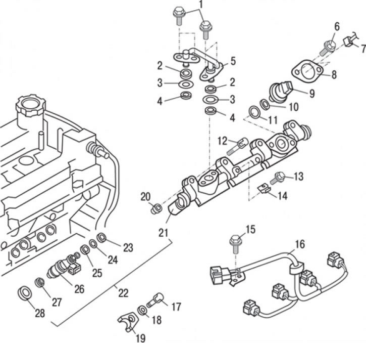
Rice. 8.12. Injectors: 1 – bolt (10–13 Nm); 2 – support ring "B"; 3 – O-ring gasket; 4 – support ring "A"; 5 – fuel pipe; 6 – bolt (22–26) Nm; 7 – fuel pressure sensor connector; 8 – flange; 9 – fuel pressure sensor; 10 – support ring; 11 – O-ring gasket; 12 – bolt (11–13 Nm); 13 – bolt (12–14 Nm); 14 – injector wiring harness support bracket; 15 – bolt (10–14 Nm); 16 – injector wiring harness; 17 – bolt (21–25 Nm); 18 – washer; 19 – nozzle holder; 20 – insulator; 21 – fuel rail; 22 – fuel rail and injector assembly; 23 – support ring "A"; 24 – O-ring gasket; 25 – support ring "B"; 26 – nozzle; 27 – figured washer; 28 – nozzle gasket
1. Disconnect the fuel pressure sensor connector 7 (Fig. 8.12).
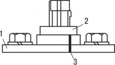
Fig. 8.13. Applying marks before removing the flange: 1 – flange; 2 – fuel pressure sensor; 3 – installation marks
2. When reusing the fuel pressure sensor, apply alignment marks on the flange and on the sensor (Fig. 8.13).
Attention! The flange ensures reliable installation of the fuel pressure sensor, taking the appropriate shape when it is secured. Therefore, before removing the sensor (and in case of its reuse), installation marks help with its subsequent installation. If a new fuel pressure sensor is installed, it must be replaced together with the flange.
3. Remove fuel pressure sensor 9, ring gasket 11 and support ring 10 (see Fig. 8.12).
Nozzles
1. Remove the air filter.
2. Remove the throttle body.
3. Remove the intake manifold.
4. Unscrew the bolts, disconnect the connectors and remove the injector wiring harness 16.
5. Unscrew the bolts and remove the injector wiring harness support bracket 14.
6. Unscrew the bolts and remove the fuel pipe 5.
7. Remove the support ring "A" 4
8. Remove the O-ring 3.
9. Remove the support ring "B" 2
10. Unscrew the bolt and remove the washer 18 and the injector holder 19.
11. Unscrew the bolts and remove the fuel rail with the injectors as an assembly without separating them.
Note: Be careful when removing the fuel rail - do not drop the injectors.
12. Unscrew the bolt and remove the insulator 20.
13. Remove the injector gaskets 16, injectors 26, shaped washers 27, support ring "A" 23, ring gasket 24 and support ring "B" 25.
Installation
Installation is carried out in the reverse order of removal, taking into account the following.
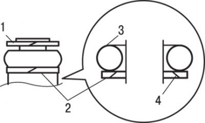
Fig. 8.9. Installing support rings and gaskets: 1 – support ring "A"; 2 – support ring "B"; 3 – O-ring gasket; 4 – beveled surface
1. Install the support rings and O-ring as shown in Fig. 8.9.
Attention! Install the support ring "B" with the beveled surface away from the back side of the ring gasket (see Fig. 8.9).
2. Make sure that the support ring "A" is installed correctly (the outer diameter of the support ring "A" is 14.8 mm). Do not confuse it with the support ring of the fuel pressure sensor.
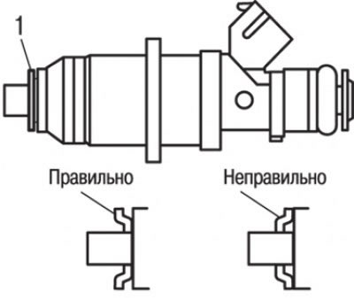
Fig. 8.14. Installing the shaped washer (1)
3. Apply plastic grease to the surface of the shaped washer to prevent it from falling during installation of the injector, install it on the injector as shown in Fig. 8.14.
Attention! The figured washer cannot be reused.
4. Apply a small amount of clean engine oil to the O-ring.
Caution: Be careful not to allow engine oil to enter the fuel rail.
5. Carefully, trying not to damage the ring gasket and turning the injector left and right, connect it to the fuel rail. After completing this operation, make sure that the injector rotates easily in its seat.
6. If the injector turns in its seat with jamming, then the O-ring may be jammed. Remove the injector, check the condition of the O-ring seal (replace it if damaged), reconnect the injector to the fuel rail and recheck the quality of assembly (the injector should easily turn in its seat).
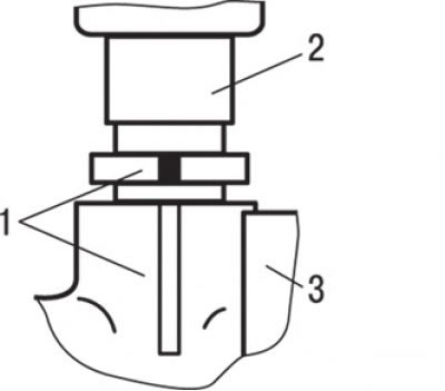
Fig. 8.15. Alignment of the installation marks (1) of the injector (2) and the fuel manifold (3)
7. Align the injector and fuel rail alignment marks (Fig. 8.15).
8. Install the injector gasket and insulator into the cylinder head.
9. Install the fuel rail assembly with injectors into the cylinder head and secure it by hand with bolts.
10. Install the injector holder and washer and tighten it to a torque of 21–25 N·m.
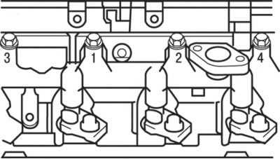
Fig. 8.16. Sequence of tightening the bolts securing the fuel manifold and injectors
11. Tighten the fuel rail assembly mounting bolts with the injectors to a torque of 11–13 N·m in accordance with the order shown in Fig. 8.16.
12. Install the support rings and O-ring (see Fig. 8.9).
Attention! Install the support ring "B" with the beveled surface away from the back side of the ring gasket (see Fig. 8.9).
13. Make sure that the support ring "A" is installed correctly (the outer diameter of the support ring "A" is 14.8 mm). Do not confuse it with the support ring of the fuel pressure sensor.
14. Apply a small amount of clean engine oil to the O-ring.
Caution: Do not allow engine oil to enter the high-pressure fuel pump or fuel rail.
15. Install the fuel pipes into the high-pressure fuel pump channels at right angles. Install the pipes carefully, avoiding twisting them, then tighten the bolts to a torque of 11–13 N·m.
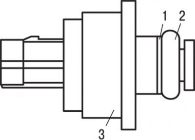
Fig. 8.17. Installing the support ring and ring gasket: 1 – support ring; 2 – O-ring gasket; 3 – fuel pressure sensor
16. Install the support ring and O-ring as shown in Fig. 8.17.
Caution! Be careful not to confuse this sealing ring with the sealing ring "A" for the injector or for the fuel pipe (the outer diameter of this sealing ring is 15.1 mm).
17. Apply a small amount of clean engine oil to the fuel pressure sensor O-ring.
Caution: Do not allow engine oil to enter the fuel rail.
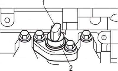
Fig. 8.18. Location of the product label (2) when installing the fuel pressure sensor (1)
[The article is reprinted from this source: MitsubishiMan.ru]
18. Install the fuel pressure sensor so that its product label with the number is positioned as shown in Fig. 8.18. If the fuel pressure sensor is reused, then before removing it, it is necessary to make installation marks on its body and flange to facilitate subsequent installation.
Attention! If a new fuel pressure sensor is installed, replace it together with the flange.
19. Install the engine protective cover.
20. Check the tightness of the fuel system.
21. Remove air from the high pressure fuel line.