



Cars produced since 1999
Removal
Disconnect the cable from the negative battery terminal.
To remove, follow these steps in sequence.
1. Drain the coolant from the engine cooling system.
2. Relieve fuel pressure (prevent fuel splashing).
3. Remove the air intake hose.
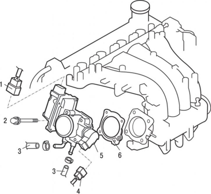
Fig. 8.19. Throttle body of cars produced since 1999: 1 – throttle servo connector; 2 – bolt (19 Nm); 3 – connection of the cooling system hose; 4 – throttle position sensor connector; 5 – throttle body; 6 – throttle body gasket
4. Disconnect the connectors of the throttle position sensor 4 (Fig. 8.19) and the throttle servo drive 1.
5. Loosen the clamps and remove the cooling system hoses 3.
6. Unscrew the bolts and remove the throttle body 5 and gasket 6.
Disassembly
To disassemble, perform the following operations in sequence.
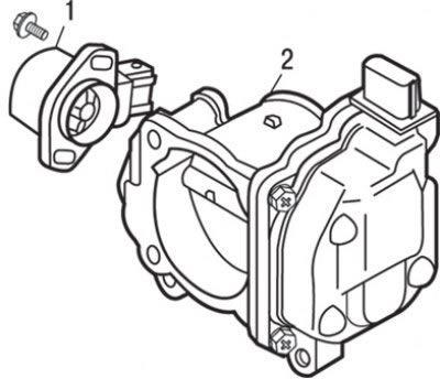
Fig. 8.20. Removing the throttle position sensor: 1 – throttle position sensor; 2 – throttle body
1. Unscrew the bolts and remove the throttle position sensor 1 (Fig. 8.20).
Assembly
For assembly, perform the following operations sequentially.
1. Position the throttle position sensor on the throttle body as shown by the dotted line in Figure 8.21.
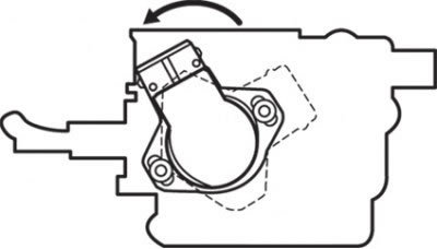
Fig. 8.21. Installing the throttle position sensor
2. Turn the throttle position sensor counterclockwise (Fig. 8.21) and tighten the sensor mounting bolts.
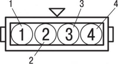
Fig. 8.22. Location of contacts on the throttle position sensor connector: 1 – power supply output to the sensor; 2 – output of the 1st channel of the throttle position sensor; 3 - "mass"; 4 – output of the 2nd channel of the throttle position sensor
3. Measure the resistance between contact "1" (Fig. 8.22) (power supply to the sensor) and contact "2" (output of the 1st channel of the throttle position sensor), as well as between contact "1" (power supply to the sensor) and contact "4" (output of the 2nd channel of the throttle position sensor).
4. When slowly opening the throttle valve from its fully closed position to its fully open position, the resistance should change smoothly in accordance with the opening angle of the throttle valve.
5. If the measured voltage value is outside the nominal values or does not change smoothly, replace the throttle position sensor.
Installation
Installation is carried out in the reverse order of removal, taking into account the following.
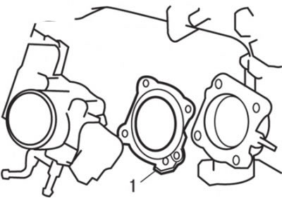
Fig. 8.23. Location of the protrusion (1) when installing the gasket
Install the gasket so that its protruding portion is located between the intake manifold and the throttle body as shown in Fig. 8.23.
When replacing the throttle body, reset the electronic throttle control system to its original condition as follows.
1. Turn the ignition key to the "ON" position and then within 1 second turn it to the "OFF" position ("LOCK–OFF"). Leave the ignition key in the "LOCK–OFF" position for at least 10 seconds.
2. Fill the engine cooling system with coolant.
3. Install the air intake hose.
Cars produced since 2001
Removal
Disconnect the cable from the negative battery terminal.
Remove the engine protective cover.
To remove, follow these steps in sequence.
1. Drain the coolant from the engine cooling system.
2. Relieve fuel pressure (prevent fuel splashing).
3. Remove the air filter.
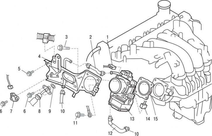
Fig. 8.24. Throttle body of cars produced since 2001: 1 – throttle position sensor connector; 2 – cooling system hose; 3 – bolt (19 Nm); 4 – throttle body support; 5 – bolt 24 Nm; 6 – bolt, 5 Nm; 7 – ignition system malfunction sensor; 8 – high pressure fuel hose connection; 9 – O-ring (lubricate); 10 – Cooling system hose connection; 11 – bolt, 9 Nm; 12 – cooling system hose; 13 – throttle body; 14 – idle speed control servo connector; 15 – throttle body gasket
4. Disconnect connectors 1 (Fig. 8.24) of the throttle position sensor and idle speed control servo drive 14.
5. Unscrew the bolts and remove the ignition system malfunction sensor 7.
6. Loosen the clamp and remove the cooling system hose 2.
7. Loosen the clamp and disconnect the cooling system hose 10.
8. Unscrew the bolts and remove the high pressure fuel hose connection 8 and the ring gasket 9.
9. Unscrew the bolts and remove the throttle body support 4.
10. Unscrew the bolts and remove the throttle body 13.
11. Loosen the clamp and disconnect the cooling system hose 12.
12. Remove gasket 15 from the throttle body.
Installation
Installation is carried out in the reverse order of removal, taking into account the following.
1. Install the gasket so that its protruding part is positioned as shown in Fig. 8.23.
2. Apply a small amount of clean engine oil to the O-ring.
Caution: Do not allow engine oil to enter the fuel rail.
3. Connect the high-pressure fuel hose to the fuel manifold by rotating it left and right, being careful not to damage the O-ring. After completing the operation, make sure that the fuel hose rotates easily.
4. If the fuel hose rotates in its seat with jamming, then the O-ring may be "bitten". Disconnect the high-pressure fuel hose, check the condition of the O-ring (if damaged, replace it), reconnect the fuel hose and check the quality of assembly (the fuel hose should rotate easily).
5. Tighten the mounting bolts to a specified torque of 5.0 N·m.