
English Русский
Български
Беларускі
Український
Српски
Hrvatski
Română
Polski
Slovenský
Magyar
Articles Bookmark Contacts Sitemap   
Company Audi Company Ford Company Hyundai Company Kia Company Mazda Company Mercedes-Benz Company Nissan
MitsubishiMan.ru


Home Colt Lancer Galant L200 Outlander Pajero Others
Carisma (1995-2004) Space Star (1998-2005)

Checking the pressure generated by the fuel pump (Mitsubishi Space Star)

  • Home
  • Mitsubishi
  • Space Star (1998-2005)
  • Power unit
  • Fuel injection system GDI
  • Checking the pressure generated by the fuel pump
0
Contents: When using a fuel pressure sensor…⤓ When using a pressure gauge ⤓
1. Reduce the pressure in the fuel system.

Warning: Before disconnecting the fuel lines, relieve the pressure in the fuel system, otherwise pressurized fuel will leak out of the fuel system.


2. Disconnect the high-pressure fuel hose from the fuel pump (high-pressure side) (Fig. 6.11).
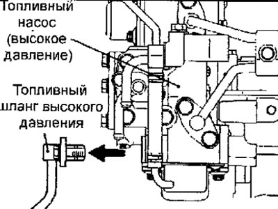


Fig. 6.11. The place where the high-pressure fuel hose is disconnected from the fuel pump on a vehicle manufactured since 1999
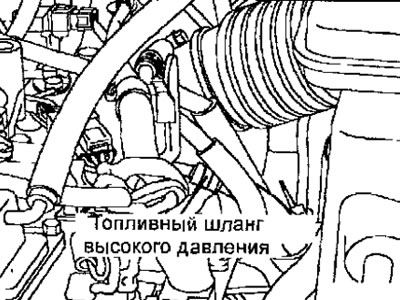


Fig. 6.12. The place where the high-pressure fuel hose is disconnected from the fuel pump on a vehicle manufactured since 2000


Warning: Cover the hose disconnection area with a towel to prevent fuel under residual pressure from splashing out.


3. Unscrew the coupling and bypass bolt from the special tool (transition hose) and connect the special tool to the transition hose instead (Fig. 6.13).
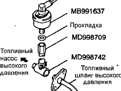


Fig. 6.13. Assembly of fuel pressure measuring instruments


4. Install the assembled special fuel pressure measuring tool.

When using a fuel pressure sensor (special tool)


  • (1) Install the special tool (for measuring pressure) between the high-pressure fuel hose and the high-pressure fuel pump.
  • (2) Connect the fuel pressure sensor to the special fuel pressure measuring tool with a spacer between them.
  • (3) Connect the fuel pressure sensor wire to the power source (cigarette lighter) and to the MUT-II device.

When using a pressure gauge


  • (1) Install the pressure gauge on the special pressure measuring instrument, placing a sealing ring or gasket between them (Fig. 6.14).
  • (2) Install the special tool with pressure gauge assembly between the high pressure fuel hose and the high pressure fuel pump.
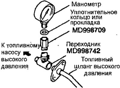


Fig. 6.14. Assembly of special tools and pressure gauge for measuring fuel pressure


5. Connect the MUT-II device to the diagnostic connector.

Warning: Before disconnecting or connecting the MUT-II, turn off the ignition to avoid damage.


6. Turn the ignition switch to the ON position, but do not start the engine.

7. Select # 07 from the MUT-II Actuator test menu to activate the low-pressure fuel pump (on the fuel tank side). Make sure that there are no leaks at the connection points.

8. Turn off the Actuator test mode or turn the ignition switch key to the OFF position.

9. Start the engine and let it idle.

10. With the engine idling, measure the fuel pressure.

Nominal pressure: about 324-343 kPa

11. Make sure that the fuel pressure at idle does not drop even after pressing the accelerator pedal several times.

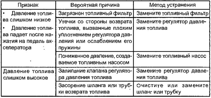
12. If any fuel pressure is out of tolerance, diagnose and repair according to the Fuel System Pressure Diagnostic Chart.

13. Stop the engine and read the fuel pressure value on the pressure gauge, which should not change.

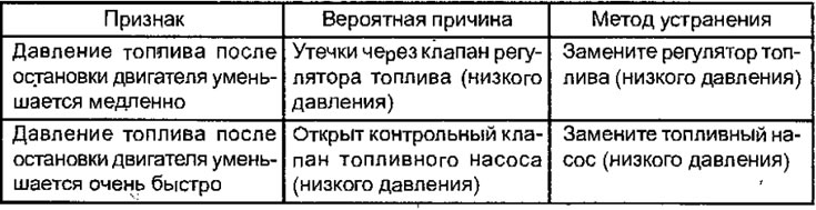
If the fuel pressure has dropped significantly after 2 minutes, diagnose and repair according to the Fuel System Pressure Drop Diagnosis Table.

Fuel System Pressure Diagnostic Chart


Fuel System Pressure Loss Diagnostic Chart


14. Reduce the residual fuel pressure in the fuel system.


15. Remove the pressure gauge and special tools from the fuel distribution line. Cover the connection with a towel to prevent fuel from splashing out due to residual pressure in the fuel line.

16. Replace the sealing ring at the end of the high-pressure fuel hose. Before installing the ring, lubricate its surface with a layer of engine oil.

17. Connect the high-pressure fuel hose to the fuel distribution line and tighten the flange mounting bolts to the specified torque.

18. Check the fuel system for leaks.

19. Disconnect MUT-II from the diagnostic connector.
This article is available at: russian, bulgarian, belarusian, ukrainian, serbian, croatian, romanian, polish, slovak, hungarian
This article was reviewed by: Miroslav Rakov
Share with friends:
◀ Previous
Space Star: Fuel injection system GDI
Next ▶

Adjusting the accelerator pedal position sensor on a car manufactured since 2000
Adjusting the accelerator pedal position sensor on a car manufactured since 1999
Adjusting the throttle position sensor
Cleaning the throttle assembly
Freeze Frame data on a vehicle manufactured since 2000
Measuring fuel pressure on the line between the high-pressure fuel pump and the injectors
Checking the fuel system for leaks
Reducing pressure in the fuel system
Checking the operation of the fuel pump
Checking the fuel pump pressure control relay and throttle actuator
Similar materials for other Mitsubishi models

➤ Checking the fuel pressure between the high pressure fuel… Mitsubishi Colt 4 and 5 (1991-2003)
➤ High pressure fuel pump (HPFP) Mitsubishi Lancer 3 and 5 (1984-1992)
➤ Checking the fuel pump, measuring the fuel pressure Mitsubishi Galant 6 and 7 (1987-1998)
➤ Fuel supply control valve to the high-pressure fuel pump Mitsubishi L200 4 (2005-2014, diesel)
➤ Checking the opening pressure of the radiator cap valve Mitsubishi Outlander 1 (2003-2008)
➤ Checking fuel pressure Mitsubishi Pajero 4 (2006-2021)
Link in different formats to this article
Comments and feedback from visitors
No comments yet


Add up two numbers 19 + 10


Carisma (1995-2004) 
  • General information
  • User manual
  • Maintenance
  • Power unit
  • Petrol engines 4G9
  • Diesel engines FBQT
  • Diesel engines F9Q
  • Cooling system
  • Injection system (MPI)
  • Injection system (GDI)
  • Engine electrical equipment
  • Transmission
  • Clutch
  • Mechanical gearbox
  • Automatic gearbox
  • Chassis and running gear
  • Steering
  • Brake system
  • Front suspension and shafts
  • Rear suspension
  • Body and interior
  • Exterior (external elements)
  • Interior (internal elements)
  • Doors, locks and windows
  • Air conditioner
  • Electrical equipment
  • Equipment and devices
  • Headlights and lighting
  • Electrical circuits
Space Star (1998-2005) 
  • General information
  • User manual
  • Maintenance
  • Power unit
  • Petrol engines 4G9
  • Petrol engines 4G1
  • Diesel engines F9Q1
  • Cooling system
  • Fuel injection system GDI
  • Fuel injection system MPI
  • Diesel supply system F9Q1
  • Ignition system
  • Diesel preheating
  • Transmission
  • Clutch
  • Mechanical gearbox
  • Automatic gearbox
  • Chassis and running gear
  • Suspension and drive shafts
  • Brake system
  • Steering
  • Body and interior
  • Exterior (external elements)
  • Interior (internal elements)
  • Doors, locks and windows
  • Heating and air conditioning
  • Electrical equipment
  • Power devices
  • Equipment and devices
MitsubishiMan.ru © 2018–2026 • Mobile version • Articles about Mitsubishi • Contacts • Sitemap: EN BG BY UA RS HR RO PL SK HU • Site search • Bookmark
Colt 2 and 3 (1983-1993) · Colt 4 and 5 (1991-2003) · Colt 5 (1995-2003) · Lancer 3 and 5 (1984-1992) · Lancer 9 (2000-2007) · Galant 5 (1983-1989) · Galant 6 and 7 (1987-1998) · L200 4 (2005-2014) · Outlander 1 (2003-2008) · Pajero 1 and 2 (1982-1999) · Pajero 4 (2006-2021) · Carisma (1995-2004) · Space Star (1998-2005) ·
This resource sets cookies 🍪 to avoid bothering you with repeated data entry.