



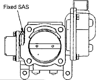
Fig. 6.3. Position of the engine crankshaft speed adjustment screw at idle (fixed SAS)
1. Connect the MUT-II device to the diagnostic connector.
2. Disconnect the connector from the throttle position sensor (Fig. 6.4).
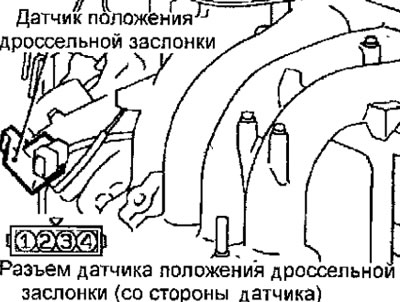
Fig. 6.4. Location of the throttle position sensor connector
3. Turn on the ignition, but do not start the engine.
4. Check the output voltage value of the throttle position sensor (channel 1) when the throttle valve is fully closed with your finger.
Sensor output voltage: 0.4-0.6 V
5. If the measured value does not correspond to the nominal voltage value, loosen the sensor mounting bolts and adjust its position by turning it in one direction or the other (Fig. 6.5). After adjustment, tighten the bolts.
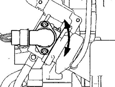
Fig. 6.5. Adjusting the throttle position sensor
6. Check the output voltage value of the throttle position sensor (2nd channel) when the throttle valve is fully closed with your finger.
Sensor output voltage: 4.2-4.8V
7. If the measured value does not match the standard voltage value, replace the throttle position sensor.
8. Turn off the ignition.
9. Connect the connector to the throttle position sensor.
10. Disconnect the MUT-II device from the diagnostic connector.
11. Use the MUT-II to clear the diagnostic trouble codes or disconnect the negative battery cable for 10 seconds, then reconnect it to the negative battery cable.
12. Turn on the ignition, wait 10 minutes and turn off the ignition. Also, if you disconnected the negative battery cable in step 11, start the engine and let it idle for 10 minutes.