



Contents: Removal ⤓ Installation ⤓
Removal
- Reduce the pressure in the fuel system.
- Remove the bolts and remove the engine cover.
- Disconnect the connector from the fuel pressure sensor (Fig. 6.49).
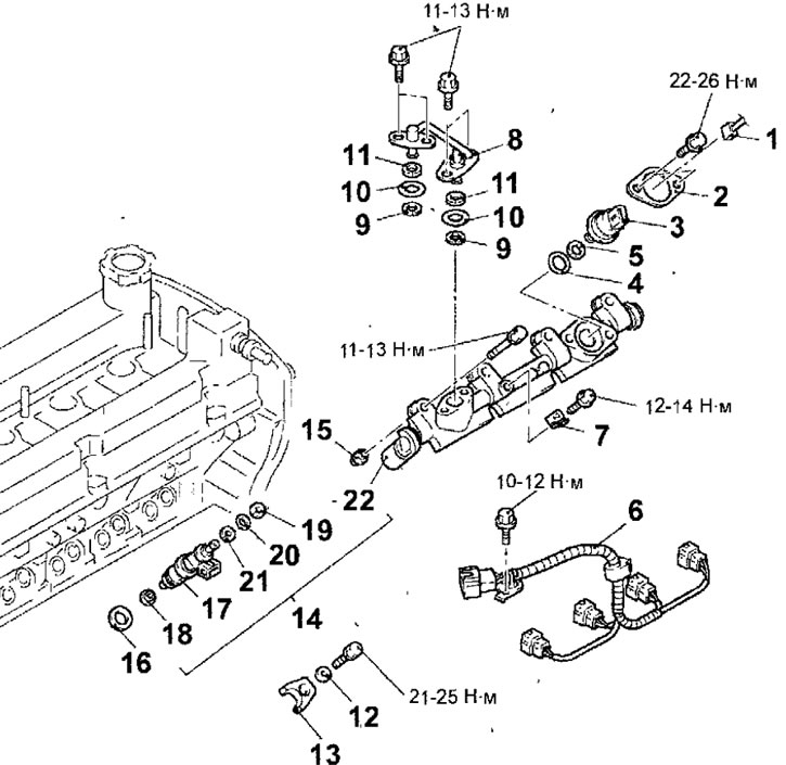
Fig. 6.49. Fuel injectors of the engine since 2000: 1 - fuel pressure sensor connector; 2 - flange; 3 - fuel pressure sensor; 4 - sealing ring; 5 - support ring; 6 - Fuel injector wiring harness; 7 - Fuel injector wiring harness mounting bracket; 8 - fuel pipe; 9 - support ring A; 10 - sealing ring; 11 - support ring B;12-washer; 13- nozzle holder; 14-fuel distribution line and injectors; 15-support; 16 - nozzle gasket; 17-fuel injector; 18 - figured washer; 19 - support ring A; 20 - sealing ring; 21 - support ring B; 22 - fuel distribution line
- If the fuel pressure sensor is to be reinstalled, mark and indicate the relative positions of the flange and sensor before removing the flange (see fig. 6.34). Unscrew the bolts and remove the fuel pressure sensor mounting flange.
Note: When tightening the flange mounting bolts, the flange will be deformed, which will keep the sealing condition and the installation position of the sensor in good condition. Therefore, it is necessary to apply installation marks to install the flange and the sensor in the original position. When replacing the fuel pressure sensor, also replace the flange.
- Remove the fuel pressure sensor.
- Remove the air filter.
- Remove the intake manifold.
- Remove the throttle assembly.
- Remove the bolt and bracket securing the fuel injector wiring harness. Disconnect the connectors and remove the fuel injector wiring harness.
- Remove the bolts and fuel line.
- Unscrew the shank, remove the washers and injector holders.
- Unscrew the bolts and remove the fuel distribution line together with the injectors installed on it. Be careful not to drop the injectors when removing the fuel distribution line.
- Carefully remove the fuel injectors from the fuel rail.
Installation
- Installation is carried out in the reverse order of removal, taking into account the following.
- Install the support rings and sealing ring onto the injector as shown figure 6.36.
The original was published on the website: MITSUBISHIMAN
Warnings.
- 1. Install the support ring B so that the beveled surface of the ring is located on the side opposite the sealing ring.
- 2. Make sure that the support ring A is installed correctly (the outer diameter of the support ring A is 14.8 mm). Do not confuse it with the support ring of the pressure sensor.
- Install the shaped washer onto the fuel injector.
Warnings!
- 1. When installing, it is necessary to use new shaped washers.
- 2. There should be no scratches, particles or foreign materials on the surface of the shaped washers.
- 3. When installing the shaped washers, strictly observe the installation direction (Fig. 6.45).
- To secure the shaped washer to the fuel injector, apply consistent grease to the surface of the shaped washer.
- Lubricate the fuel injector sealing rings with a thin layer of engine oil (Fig. 6.46).
Warning: When removing and installing the fuel line, prevent engine oil from getting into it.
- Being careful not to damage the sealing ring, insert the fuel injector into the fuel line by turning it back and forth and make sure that the injector turns easily in its seat.
- If the nozzle turns in its socket with sticking, the sealing ring may be jammed.
- Remove the fuel injector and check the sealing ring for damage, replacing it if necessary. Reinstall the fuel injector into the fuel line and recheck that the injector rotates easily in its seat.
- Align the fuel injector and fuel line alignment marks (Fig. 6.47).
- Install the injector gaskets and bushings into the cylinder head.
- Install the fuel line together with the fuel injectors and secure it with the bolts, temporarily tightening them by hand.
- Install the injector holders and secure with bolts, tightening them to the required torque.
Tightening torque: 21-25 Nm
- Tighten the fuel line mounting bolts to the required torque in the sequence shown in Figure 6.50.
Tightening torque: 11-13 Nm
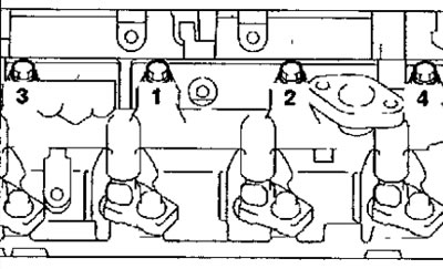
Fig. 6.50. Sequence of tightening the fuel line mounting bolts
- Install the support rings and sealing ring on the fuel pipe as shown in Figure 6.36.
Warnings!
- 1. Install the support ring B so that the beveled surface of the ring is located on the side opposite the sealing ring.
- 2. Make sure that the support ring A is installed correctly (the outer diameter of the support ring A is 14.8 mm). Do not confuse it with the support ring of the pressure sensor.
- Lubricate the fuel line sealing rings with engine oil. Do not allow oil to enter the high-pressure fuel pump or fuel line.
- Install the fuel pipe and secure with bolts, tightening them to the required torque.
Tightening torque: 11-13 Nm
- Install the support and seal rings on the fuel pressure sensor as shown in Figure 6.39.
Warning: Make sure that the support ring (outer diameter of support ring A is 15.1 mm) is installed correctly. Do not confuse it with the support ring of the injector, fuel supply pipe and fuel return pipe.
- Lubricate the fuel pressure sensor sealing ring with engine oil. Do not allow oil to enter the fuel pressure regulator.
- Align the marks made before removing the sensor and install the fuel pressure sensor and flange on the fuel pressure regulator (Fig. 6.51). When replacing the fuel pressure sensor, also replace the flange.
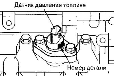
Fig. 6.51 Installing the fuel pressure sensor