



Removal
- Reduce the pressure in the fuel system.
Warning: Before disconnecting the fuel lines, relieve the pressure in the fuel system, otherwise pressurized fuel will leak out of the fuel system.
- Remove the bolts and remove the engine cover.
- Remove the air filter.
- Remove the throttle assembly.
- Remove the intake manifold.
- Loosen the clamps and disconnect the fuel return hoses (Fig. 6.40).
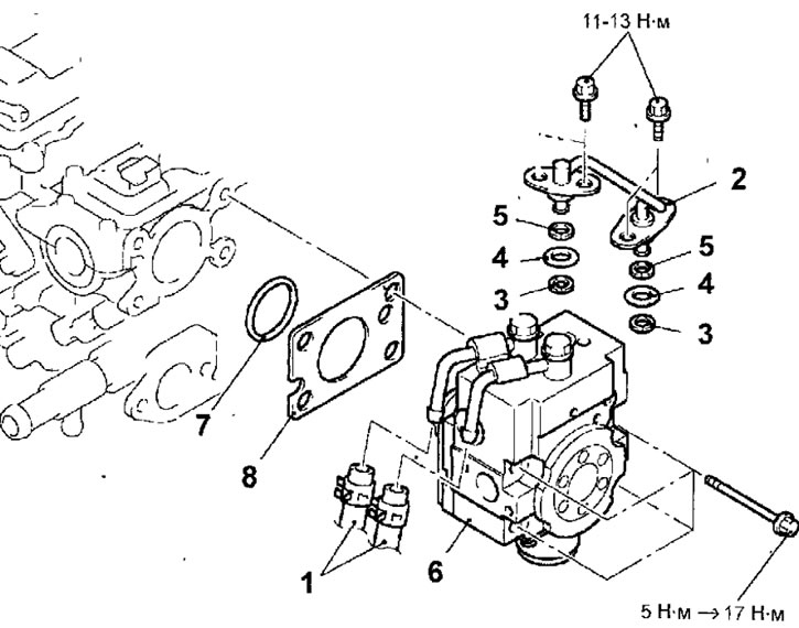
Fig. 6.40. High-pressure fuel pump of the engine since 2000: 1 - fuel return hoses; 2 - fuel pipe; 3 - support ring A; 4 - sealing ring; 5 - support ring B; 6 - high pressure fuel pump; 7 - sealing ring; 8 - gasket
- Remove the bolts and fuel line.
- Remove the bolts and high pressure fuel pump, sealing ring and gasket.
Installation
- Installation is carried out in the reverse order of removal, taking into account the following.
- Before installing the high-pressure fuel pump, lubricate the roller and sealing ring of the fuel pump with engine oil (Fig. 6.41).
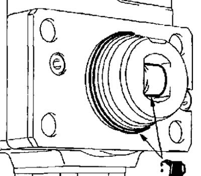
Fig. 6.41. Lubrication points of the fuel pump roller and sealing ring
- Install the fuel pump to the engine and temporarily secure it with bolts, tightening them by hand. Final tightening of the bolts should be done later.
- Install the support rings and sealing ring as shown figure 6.36.
Warnings
- 1. Install the support ring B so that the beveled surface of the ring is located on the side opposite the sealing ring,
- 2. Make sure that the support ring A is installed correctly (the outer diameter of the support ring A is 14.8 mm). Do not confuse it with the support ring of the pressure sensor.
- When installing the fuel pipes, lubricate the O-ring with a small amount of engine oil.
Warning: Do not allow oil to enter the fuel pump, fuel pressure regulator or fuel line.
- Install the fuel pipe into the fuel pump and fuel rail channels and secure with bolts, tightening them to the specified torque.
Tightening torque: 11-13 Nm
- To tighten the fuel pump mounting bolts, use a torque wrench that provides a tightening accuracy of 0.5 N·m. Tighten the fuel pump mounting bolts in the sequence shown in Figure 6.42. as follows.
1. Tighten the bolts to 5 Nm.
2. Tighten the bolts to a torque of 17 N·m. The difference in tightening torque between the four bolts must not exceed 2 N·m.
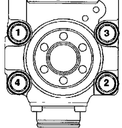
Fig. 6.42. Sequence of tightening the fuel pump mounting bolts
- Install the fuel return hoses so that the marks on the hoses are in the position shown in Figure 6.43.
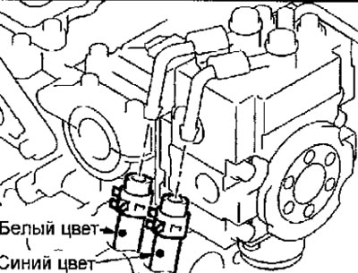
Fig. 6.43. Installation position of fuel return hoses
Bleeding air from the high pressure fuel pump
- Start the engine and let it run for 15 seconds at 2000 rpm, this will remove air from the fuel pump.
Note: Air may enter the fuel pump when it is removed. If air enters the pump, DTC 56 will be displayed.
- Use the MUT-II to confirm the diagnostic trouble code. If trouble code 56 is stored in the engine control unit memory, erase it.
[Original source of information: mitsubishiman.ru]