
English Русский
Български
Беларускі
Український
Српски
Hrvatski
Română
Polski
Slovenský
Magyar
Articles Bookmark Contacts Sitemap   
Company Audi Company Ford Company Hyundai Company Kia Company Mazda Company Mercedes-Benz Company Nissan
MitsubishiMan.ru


Home Colt Lancer Galant L200 Outlander Pajero Others
Carisma (1995-2004) Space Star (1998-2005)

Disassembly and assembly of the throttle unit of the engine since 1999 (Mitsubishi Space Star)

  • Home
  • Mitsubishi
  • Space Star (1998-2005)
  • Power unit
  • Fuel injection system GDI
  • Disassembly and assembly of the throttle unit of the engine since 1999
0
Contents: Disassembly ⤓ Assembly ⤓

Disassembly


  • Remove the throttle assembly.
  • Remove the screws and throttle position sensor (Fig. 6.53).
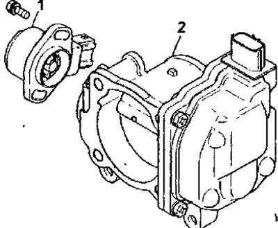


Fig. 6.53. Throttle assembly of the engine since 1999: 1 - throttle position sensor; 2 - throttle assembly


Assembly


  • Assembly is carried out in the reverse order of disassembly, taking into account the following.

Warnings
  • Do not attempt to change the position of the engine's idle speed control (SAS) screw. This screw is factory-installed with high precision and requires no adjustment.
  • If such interference occurs, adjust it.
  • Do not disassemble the throttle position sensor.

  • Install the throttle position sensor on the throttle assembly in the position shown by the dotted line in Figure 6.54.
  • To install the throttle position sensor, turn it counterclockwise and secure it with screws (see Fig. 6.54).
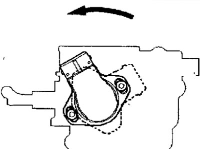


Fig. 6.54. Installing the throttle position sensor on the throttle assembly


  • Measure the voltage between pin 1 (sensor power supply) and pin 2 (output signal of channel 1 of the throttle position sensor), and between pin 1 (sensor power supply) and pin 4 (output signal of channel 2 of the throttle position sensor) (Fig. 6.55). Make sure that when the throttle valve opens from the fully closed to the fully open position, the sensor resistance changes smoothly in accordance with the throttle valve opening angle.
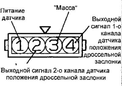


Fig. 6.55. Throttle position sensor connector pin locations

  • If the resistance does not change smoothly, replace the throttle position sensor.
This article is available at: russian, bulgarian, belarusian, ukrainian, serbian, croatian, romanian, polish, slovak, hungarian
This article was reviewed by: Miroslav Rakov
Share with friends:
◀ Previous
Space Star: Fuel injection system GDI
Next ▶

Throttle body of the engine since 1999
Fuel injectors for engines produced since 2000
Fuel injectors for engines manufactured since 1999
High pressure fuel pump for engines manufactured since 2000
High pressure fuel pump for engines manufactured since 1999
Throttle body of the engine since 2000
Disassembly and assembly of the throttle unit of the engine since 2000
Injector control pulse generator
Fuel tank
Technical data of the GDI fuel injection system
Similar materials for other Mitsubishi models

➤ Engine diagnostics using a vacuum gauge, compression… Mitsubishi Colt 2 and 3 (1983-1993)
➤ Electronic engine control unit Mitsubishi Lancer 9 (2000-2007, petrol)
➤ Starting the engine from an auxiliary power source Mitsubishi Galant 6 and 7 (1987-1998)
➤ Electronic Engine Control Unit (ECU) Mitsubishi L200 4 (2005-2014, diesel)
➤ Electronic immobilizer (engine start blocking system) Mitsubishi Outlander 1 (2003-2008)
➤ Tachometer (engine speed) Mitsubishi Pajero 1 and 2 (1982-1999)
Link in different formats to this article
Comments and feedback from visitors
No comments yet


Add up two numbers 24 + 36


Carisma (1995-2004) 
  • General information
  • User manual
  • Maintenance
  • Power unit
  • Petrol engines 4G9
  • Diesel engines FBQT
  • Diesel engines F9Q
  • Cooling system
  • Injection system (MPI)
  • Injection system (GDI)
  • Engine electrical equipment
  • Transmission
  • Clutch
  • Mechanical gearbox
  • Automatic gearbox
  • Chassis and running gear
  • Steering
  • Brake system
  • Front suspension and shafts
  • Rear suspension
  • Body and interior
  • Exterior (external elements)
  • Interior (internal elements)
  • Doors, locks and windows
  • Air conditioner
  • Electrical equipment
  • Equipment and devices
  • Headlights and lighting
  • Electrical circuits
Space Star (1998-2005) 
  • General information
  • User manual
  • Maintenance
  • Power unit
  • Petrol engines 4G9
  • Petrol engines 4G1
  • Diesel engines F9Q1
  • Cooling system
  • Fuel injection system GDI
  • Fuel injection system MPI
  • Diesel supply system F9Q1
  • Ignition system
  • Diesel preheating
  • Transmission
  • Clutch
  • Mechanical gearbox
  • Automatic gearbox
  • Chassis and running gear
  • Suspension and drive shafts
  • Brake system
  • Steering
  • Body and interior
  • Exterior (external elements)
  • Interior (internal elements)
  • Doors, locks and windows
  • Heating and air conditioning
  • Electrical equipment
  • Power devices
  • Equipment and devices
MitsubishiMan.ru © 2018–2026 • Mobile version • Articles about Mitsubishi • Contacts • Sitemap: EN BG BY UA RS HR RO PL SK HU • Site search • Bookmark
Colt 2 and 3 (1983-1993) · Colt 4 and 5 (1991-2003) · Colt 5 (1995-2003) · Lancer 3 and 5 (1984-1992) · Lancer 9 (2000-2007) · Galant 5 (1983-1989) · Galant 6 and 7 (1987-1998) · L200 4 (2005-2014) · Outlander 1 (2003-2008) · Pajero 1 and 2 (1982-1999) · Pajero 4 (2006-2021) · Carisma (1995-2004) · Space Star (1998-2005) ·
This resource sets cookies 🍪 to avoid bothering you with repeated data entry.