
English Русский
Български
Беларускі
Український
Српски
Hrvatski
Română
Polski
Slovenský
Magyar
Articles Bookmark Contacts Sitemap   
Company Audi Company Ford Company Hyundai Company Kia Company Mazda Company Mercedes-Benz Company Nissan
MitsubishiMan.ru


Home Colt Lancer Galant L200 Outlander Pajero Others
Carisma (1995-2004) Space Star (1998-2005)

Fuel injectors for engines manufactured since 1999 (Mitsubishi Space Star)

  • Home
  • Mitsubishi
  • Space Star (1998-2005)
  • Power unit
  • Fuel injection system GDI
  • Fuel injectors for engines manufactured since 1999
0
Contents: Removal ⤓ Installation ⤓

Removal


  • Reduce the pressure in the fuel system.
  • Remove the bolts and remove the engine cover.
  • Remove the air filter.
  • Remove the intake manifold.
  • Unscrew the bolts and remove the fuel line fastening clamps (Fig. 6.44).
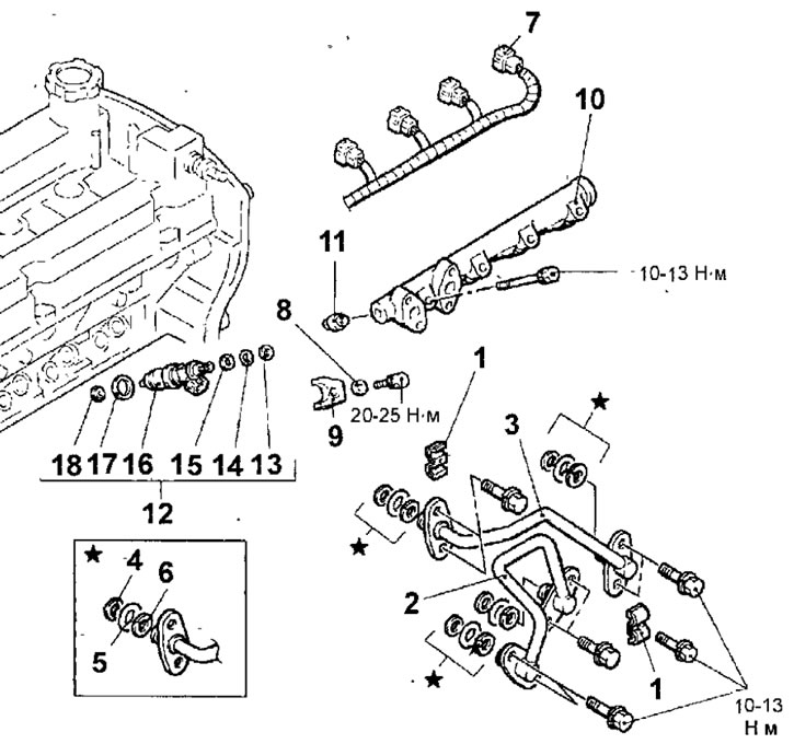


Fig. 6.44. Fuel injectors of the engine since 1999: 1 - fuel line fastening clamp; 2 - fuel supply pipe; 3 - Fuel return pipe; 4 - support ring A; 5 - sealing ring; 6 - support ring B; 7 - fuel injector connector; 8 - washer; 9 - nozzle holder; 10 - fuel distribution line; 11 - support; 12 - fuel injector; 13 - support ring;14 - sealing ring; 15 - support ring; 16 - fuel injector; 17 - gasket; 18 - figured washer

  • Remove the bolts and fuel supply pipe.
  • Remove the bolts and fuel return pipe.

Warning: Before disconnecting the connectors from the fuel injectors, disconnect the negative battery cable.

  • Disconnect the connectors from the fuel injectors.
  • Remove the bolts, washers and injector holders.
  • Unscrew the bolts and remove the fuel distribution line together with the injectors installed on it.

Caution: Be careful not to drop the injectors when removing the fuel rail.


  • Carefully remove the fuel injectors from the fuel rail.

Installation


Installation is carried out in the reverse order of removal, taking into account the following.

Warnings
  • 1. When installing, it is necessary to use new shaped washers.
  • 2. There should be no scratches or foreign particles on the surface of the shaped washers.
  • 3. When installing the shaped washers, strictly observe the installation direction (Fig. 6.45).
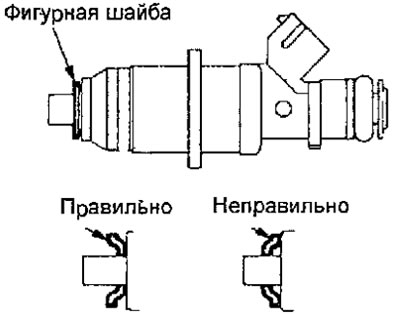


Fig. 6.45. Direction of installation of the shaped washer on the fuel injector

  • To secure the shaped washer to the fuel injector, apply consistent grease to the surface of the shaped washer.
  • Lubricate the fuel injector sealing rings with a thin layer of engine oil (Fig. 6.46).
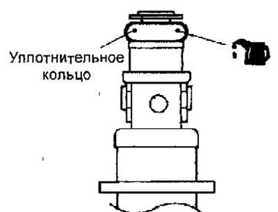


Fig. 6.46. Location of sealing rings on the fuel injector


Warning: When removing and installing the fuel line, prevent engine oil from getting into it.

  • Being careful not to damage the sealing ring, insert the fuel injector into the fuel line by turning it back and forth and make sure that the injector turns easily in its seat.
  • If the injector turns in its seat with sticking, the sealing ring may be "bitten". Remove the fuel injector and check the condition of the sealing ring and, if there is damage, replace it. Reinstall the fuel injector in the fuel line and check that the injector turns easily in its seat.
  • Align the fuel injector and fuel line alignment marks (Fig. 6.47).
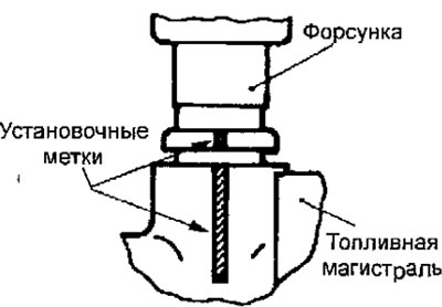


Fig. 6.47. Alignment of the installation marks on the fuel injector and fuel line

  • Install the fuel line together with the fuel injectors and secure it with the bolts, tightening them to the required torque.
  • Install the support and sealing rings as shown figure 6.36.

Warnings
  • 1. Install the support ring B so that the beveled surface of the ring is located on the side opposite the sealing ring.
  • 2. Make sure that the support ring A is installed correctly (the outer diameter of the support ring A is 14.8 mm). Do not confuse it with the support ring of the pressure sensor.

  • Lubricate the sealing rings of the fuel supply and return pipes with engine oil (Fig. 6.48).
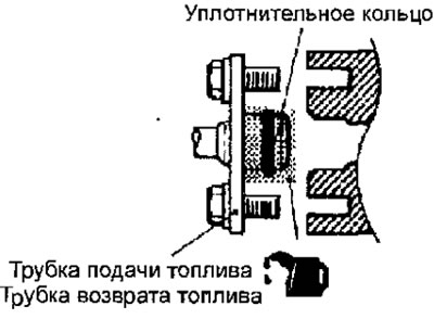


Fig. 6.48. Installing fuel supply and return pipes


Warning: Do not allow oil to enter the fuel pressure regulator or fuel line.

  • Install the fuel supply and return pipes and secure with bolts, tightening them to the required torque.
  • Install the fuel line clamps and secure with bolts, tightening them to the required torque.
  • Connect the connectors to the fuel injectors.
  • Install the intake manifold.
  • Install the air filter.
  • Install the engine cover.
  • Start the engine and check for fuel leaks from the fuel system.

(The article is based on data from the website: MitsubishiMan)
This article is available at: russian, bulgarian, belarusian, ukrainian, serbian, croatian, romanian, polish, slovak, hungarian
This article was reviewed by: Miroslav Rakov
Share with friends:
◀ Previous
Space Star: Fuel injection system GDI
Next ▶

High pressure fuel pump for engines manufactured since 2000
High pressure fuel pump for engines manufactured since 1999
Checking the Clutch Pedal Position Switch
Checking the throttle servo
Checking fuel injectors
Fuel injectors for engines produced since 2000
Throttle body of the engine since 1999
Disassembly and assembly of the throttle unit of the engine since 1999
Throttle body of the engine since 2000
Disassembly and assembly of the throttle unit of the engine since 2000
Similar materials for other Mitsubishi models

➤ Replacing the fuel filter of gasoline engines Mitsubishi Colt 4 and 5 (1991-2003)
➤ Removal Water from a Diesel Fuel Filter / Replacing a Fuel… Mitsubishi Lancer 3 and 5 (1984-1992)
➤ Removal and installation of fuel lines and injection… Mitsubishi Galant 6 and 7 (1987-1998)
➤ Fuel injectors Mitsubishi L200 4 (2005-2014, diesel)
➤ Fuel selection Mitsubishi Outlander 1 (2003-2008)
➤ Diagnostics and cleaning of fuel injectors Mitsubishi Pajero 4 (2006-2021)
Link in different formats to this article
Comments and feedback from visitors
No comments yet


Add up two numbers 21 + 37


Carisma (1995-2004) 
  • General information
  • User manual
  • Maintenance
  • Power unit
  • Petrol engines 4G9
  • Diesel engines FBQT
  • Diesel engines F9Q
  • Cooling system
  • Injection system (MPI)
  • Injection system (GDI)
  • Engine electrical equipment
  • Transmission
  • Clutch
  • Mechanical gearbox
  • Automatic gearbox
  • Chassis and running gear
  • Steering
  • Brake system
  • Front suspension and shafts
  • Rear suspension
  • Body and interior
  • Exterior (external elements)
  • Interior (internal elements)
  • Doors, locks and windows
  • Air conditioner
  • Electrical equipment
  • Equipment and devices
  • Headlights and lighting
  • Electrical circuits
Space Star (1998-2005) 
  • General information
  • User manual
  • Maintenance
  • Power unit
  • Petrol engines 4G9
  • Petrol engines 4G1
  • Diesel engines F9Q1
  • Cooling system
  • Fuel injection system GDI
  • Fuel injection system MPI
  • Diesel supply system F9Q1
  • Ignition system
  • Diesel preheating
  • Transmission
  • Clutch
  • Mechanical gearbox
  • Automatic gearbox
  • Chassis and running gear
  • Suspension and drive shafts
  • Brake system
  • Steering
  • Body and interior
  • Exterior (external elements)
  • Interior (internal elements)
  • Doors, locks and windows
  • Heating and air conditioning
  • Electrical equipment
  • Power devices
  • Equipment and devices
MitsubishiMan.ru © 2018–2026 • Mobile version • Articles about Mitsubishi • Contacts • Sitemap: EN BG BY UA RS HR RO PL SK HU • Site search • Bookmark
Colt 2 and 3 (1983-1993) · Colt 4 and 5 (1991-2003) · Colt 5 (1995-2003) · Lancer 3 and 5 (1984-1992) · Lancer 9 (2000-2007) · Galant 5 (1983-1989) · Galant 6 and 7 (1987-1998) · L200 4 (2005-2014) · Outlander 1 (2003-2008) · Pajero 1 and 2 (1982-1999) · Pajero 4 (2006-2021) · Carisma (1995-2004) · Space Star (1998-2005) ·
This resource sets cookies 🍪 to avoid bothering you with repeated data entry.