
English Русский
Български
Беларускі
Український
Српски
Hrvatski
Română
Polski
Slovenský
Magyar
Articles Bookmark Contacts Sitemap   
Company Audi Company Ford Company Hyundai Company Kia Company Mazda Company Mercedes-Benz Company Nissan
MitsubishiMan.ru


Home Colt Lancer Galant L200 Outlander Pajero Others
Carisma (1995-2004) Space Star (1998-2005)

Self-diagnosis function. Multi-point fuel injection (MPI) system (Mitsubishi Space Star)

  • Home
  • Mitsubishi
  • Space Star (1998-2005)
  • Power unit
  • Fuel injection system GDI
  • Self-diagnosis function. Multi-point fuel injection (MPI) system
0
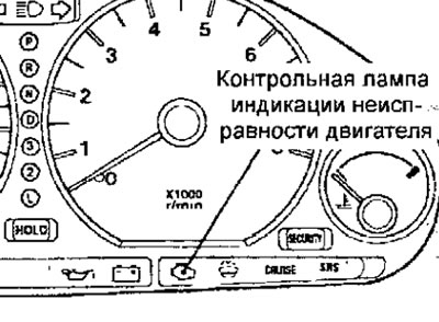
If a malfunction occurs in any of the following components of the multipoint injection (MPI) system, the engine malfunction indicator lamp comes on ("CHECK ENGINE") (Fig. 7.1).


Fig. 7.1. Location of the engine malfunction indicator lamp


If the check engine light remains on while the engine is running, check for a fault code:

However, the indicator lamp should light and remain on for 5 seconds after the ignition is turned on.

Items and conditions that may cause the Malfunction Indicator Lamp (MIL) to come on


Code Diagnosed element
— Electronic engine control unit (cars with manual transmission) or electronic engine and automatic transmission control unit (cars with automatic transmission).
P0105 Atmospheric (barometric) pressure sensor and its circuits
P0110 Intake Manifold Air Temperature Sensor and its circuits
P0115 Coolant temperature sensor and its circuits
P0120 Throttle position sensor and its circuits
P0125 Feedback system (for fuel supply) and its circuits
P0135 Front Oxygen Sensor Heating Element (Sensor 1)
P0136 Rear Oxygen Sensor (Sensor 2) and its circuits
P0141 Rear Oxygen Sensor Heating Element (Sensor 2)
P0170 Fuel supply system malfunction
P0201 Injector No.1 and its chain
P0202 Injector #2 and its chain
P0203 Injector #4 and its chain
P0300* Ignition coil (power transistor) and its circuit
P0301 Detection of misfires in cylinder 1
P0302 Detection of misfire in cylinder 2
P0303 Detection of misfire in cylinder 3
P0304 Detection of misfires in the 4th cylinder
P0335 Crankshaft position sensor and its circuits
P0340 Camshaft position sensor and its circuits
P0403 EGR valve and its electrical circuit
P0420 Catalytic converter failure
P0443 Evaporative Evaporative Blowoff Solenoid Valve and its circuits
P0505 Idle Speed Control (ISC) Servo and its Circuits


Notes
  • 1. If the warning lamp lights up due to a malfunction of the engine control unit (vehicles with manual transmission) or the engine and automatic transmission control unit (vehicles with automatic transmission), communication between the MUT-II and the engine control unit (vehicles with manual transmission) or the engine and automatic transmission control unit (vehicles with automatic transmission) is not possible and the diagnostic trouble code cannot be read.
  • 2. As soon as the electronic engine control unit (vehicles with manual transmission) or the electronic engine and automatic transmission control unit (vehicles with automatic transmission) has detected a malfunction, the engine malfunction indicator lamp lights up each time the engine is restarted and the same malfunction is indicated again. However, for the position marked with the "*" icon in the table, the indicator lamp lights up only once when the malfunction is detected for the first time.
  • The enabled control lwmpf can be disabled only if the following conditions are met:
  • (1) When the engine control unit (vehicles with manual transmission) or the engine and automatic transmission control unit (vehicles with automatic transmission) has detected a malfunction in the transmission three* times.
  • * in this case, "one time" means the period from engine start to engine stop.
  • (2) In the misfire judgment mode, when the vehicle driving conditions (engine speed, coolant temperature, etc.) are similar to the condition under which the malfunction was first detected.
  • "Sensor 1" means that the sensor is installed closer to the engine, and "Sensor 2" means that the sensor is installed further from the engine than the first one.

The source of the article is available at mitsubishiman
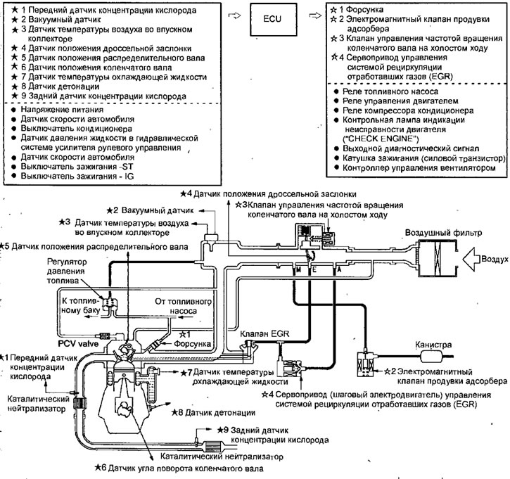


Fig. 7.2. Functional diagram of the multi-point fuel injection (MPI) system
This article is available at: russian, bulgarian, belarusian, ukrainian, serbian, croatian, romanian, polish, slovak, hungarian
This article was reviewed by: Miroslav Rakov
Share with friends:
◀ Previous
Space Star: Fuel injection system GDI
Next ▶

Technical data of the GDI fuel injection system
Fuel tank
Injector control pulse generator
Disassembly and assembly of the throttle unit of the engine since 2000
Throttle body of the engine since 2000
 
Similar materials for other Mitsubishi models

➤ Multi-Point Fuel Injection (MPI) System Mitsubishi Colt 2 and 3 (1983-1993)
➤ MPI (Multi-Point Injection) Fuel Injection Device Mitsubishi Lancer 3 and 5 (1984-1992)
➤ Fuel injection system Mitsubishi Galant 5 (1983-1989, petrol)
➤ Removal and installation the fuel injection pump pulley Mitsubishi L200 4 (2005-2014, diesel)
➤ General information about the fuel supply and injection… Mitsubishi Outlander 1 (2003-2008)
➤ Fuel injection system parts Mitsubishi Pajero 1 and 2 (1982-1999)
Link in different formats to this article
Comments and feedback from visitors
No comments yet


Add up two numbers 23 + 32


Carisma (1995-2004) 
  • General information
  • User manual
  • Maintenance
  • Power unit
  • Petrol engines 4G9
  • Diesel engines FBQT
  • Diesel engines F9Q
  • Cooling system
  • Injection system (MPI)
  • Injection system (GDI)
  • Engine electrical equipment
  • Transmission
  • Clutch
  • Mechanical gearbox
  • Automatic gearbox
  • Chassis and running gear
  • Steering
  • Brake system
  • Front suspension and shafts
  • Rear suspension
  • Body and interior
  • Exterior (external elements)
  • Interior (internal elements)
  • Doors, locks and windows
  • Air conditioner
  • Electrical equipment
  • Equipment and devices
  • Headlights and lighting
  • Electrical circuits
Space Star (1998-2005) 
  • General information
  • User manual
  • Maintenance
  • Power unit
  • Petrol engines 4G9
  • Petrol engines 4G1
  • Diesel engines F9Q1
  • Cooling system
  • Fuel injection system GDI
  • Fuel injection system MPI
  • Diesel supply system F9Q1
  • Ignition system
  • Diesel preheating
  • Transmission
  • Clutch
  • Mechanical gearbox
  • Automatic gearbox
  • Chassis and running gear
  • Suspension and drive shafts
  • Brake system
  • Steering
  • Body and interior
  • Exterior (external elements)
  • Interior (internal elements)
  • Doors, locks and windows
  • Heating and air conditioning
  • Electrical equipment
  • Power devices
  • Equipment and devices
MitsubishiMan.ru © 2018–2026 • Mobile version • Articles about Mitsubishi • Contacts • Sitemap: EN BG BY UA RS HR RO PL SK HU • Site search • Bookmark
Colt 2 and 3 (1983-1993) · Colt 4 and 5 (1991-2003) · Colt 5 (1995-2003) · Lancer 3 and 5 (1984-1992) · Lancer 9 (2000-2007) · Galant 5 (1983-1989) · Galant 6 and 7 (1987-1998) · L200 4 (2005-2014) · Outlander 1 (2003-2008) · Pajero 1 and 2 (1982-1999) · Pajero 4 (2006-2021) · Carisma (1995-2004) · Space Star (1998-2005) ·
This resource sets cookies 🍪 to avoid bothering you with repeated data entry.