
Fuel is drawn from the fuel tank by an electric fuel pump and fed through the fuel filter to the distribution line and then to the injection valves. The pressure regulator on the line ensures the constancy of pressure in the fuel system with changes in the suction vacuum pressure. The intake air is cleaned in the air filter and fed into the engine through the intake manifold.
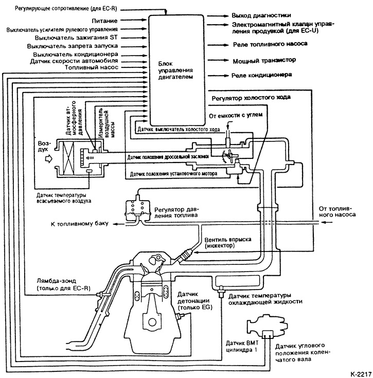
An air mass meter is located in the air filter housing, which measures the amount of incoming air and transmits this information to the control unit in the form of electrical impulses. Based on these pulses and the engine speed signals, the engine control unit roughly calculates the fuel injection timing. Signals from other sensors, such as the atmospheric pressure meter or the intake air temperature sensor, are also used to determine the injection timing more precisely.
The injection / ignition system control unit processes the data from the sensors and calculates the injection timing and the amount of injected fuel based on the parametric field stored in its memory. With a longer opening of the injection valve (injector) More fuel will be injected per revolution of the crankshaft. Injection is sequential, i.e. the injection valves are controlled separately in the ignition sequence.
Lambda probe (oxygen sensor) measures the oxygen content in the exhaust gases and transmits the information to the control unit in the form of voltage. Based on this information, the control unit changes the ratio between the fuel and air in the mixture so that the exhaust gases burn out in the catalyst in an optimal way.
The fuel tank air release valve is controlled depending on the engine operating mode. The evaporating fuel in the fuel tank is collected in the activated carbon filter and expelled through the combustion valve. Thus, fuel vapors are mostly used economically and are not released into the air.
Diagram of the MPI injection device
The figure shows a 1.5L engine
MPI fuel supply
The figure shows a 1.5L engine
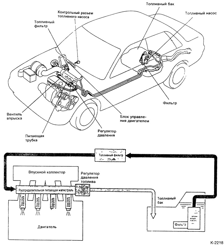
The control unit is located in the cabin on the right next to the glove compartment.
The fuel pump is located in the fuel tank and is immersed in fuel. This reduces noise and the formation of fuel bubbles. The safety valve opens at a pressure of 4.5-6 bar and thus prevents an excessive increase in pressure in the fuel line. The non-return valve maintains pressure in the fuel line when the engine is stopped at the camshaft and maintains a pressure of 3.3 bar above the pressure in the intake manifold at all times. The pressure value is therefore approx. 2.7 bar (turbo engine 2.55 bar).
Injection valves (injectors) are controlled by the control unit and during the operation of the injection device. When current flows through the solenoid winding, the injection valve needle retracts and fuel is injected. When the current circuit is broken, the spring returns the needle and the valve closes.
A throttle valve is installed in the throttle body, which regulates the amount of air through the gas pedal. In addition, there is an idle speed adjusting mechanism in the throttle body.
idle speed controller (setting motor) regulates the air supply bypassing the throttle valve. Thanks to him, the number of revolutions of the engine in the warm-up phase is stabilized. On the idle speed controller there is a position sensor for the installation motor and an idle speed switch.
Attention: when working on the injection device and fuel lines, keep clean, see point 6.2.