



Contents: Cleaning ⤓ Examination ⤓
A thorough cleaning of the cylinder head and associated valve train, followed by a detailed inspection, will help you decide what work needs to be done to the valves during an engine rebuild.
CAUTION: If the engine was severely overheated, the cylinder head is likely warped.
Cleaning
Remove all traces of old gasket material and sealant from the mating surfaces of the cylinder head and the intake and exhaust manifolds. Be very careful. Solvents are available from auto parts stores that soften the gasket material and make it easier to remove.
Remove dirt from the coolant passages.
Use a stiff brush to clean out the various openings to remove any sediment that may have formed in them.
Screw a bolt or stud of the appropriate diameter into each tapped hole to remove any corrosion or sealant that may be present. If you have a source of compressed air, use it to clear any debris from the hole.
CAUTION: When working with compressed air, wear protective glasses!
Clean the head bolt holes with a stiff wire brush.
Wash the cylinder head with solvent and dry it thoroughly. Compressed air will speed up this process and ensure that all holes and openings are clean.
CAUTION: Special deposit removers may be useful when cleaning. These are highly alkaline and should be used with caution. Read the instructions on the packaging carefully before starting work.
Clean the camshaft and valve train components with solvent and dry thoroughly. Do not mix them up during the cleaning process. Compressed air will speed up the process and ensure that the oil passage holes are clean.
Clean all valve springs, seats, crackers and tappets with solvent and dry thoroughly. Clean one valve at a time and do not mix up their associated parts.
Remove any carbon deposits that have formed on the valves using a brush.
Examination
CAUTION: Be sure to perform all of the following checks before determining whether processing (grinding) is necessary. Make a list of the parts that need attention.
Cylinder head
Check the head very carefully for cracks, signs of coolant leakage and other damage. If cracks are found, consult with specialists, repair is possible. If repair is not possible, you should purchase a new cylinder head.
Using a straight edge and a feeler gauge, check the contact surface of the head for roughness. If the roughness exceeds the limit, the surface can be ground in the workshop.
Check the valve seats in each combustion chamber. If they are dented, cracked or burnt, the seats need to be treated or replaced.
Measure the valve clearance in the direction perpendicular to its axis. The distance from the valve plate to the valve seat should be about 25 mm.
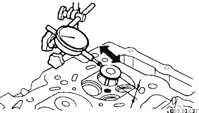
The maximum allowable clearance is 0.2 mm. If the clearance exceeds the specified limit, check the clearance between the valve and the guide sleeve by measuring the inner diameter of the sleeve and the outer diameter of the valve stem.
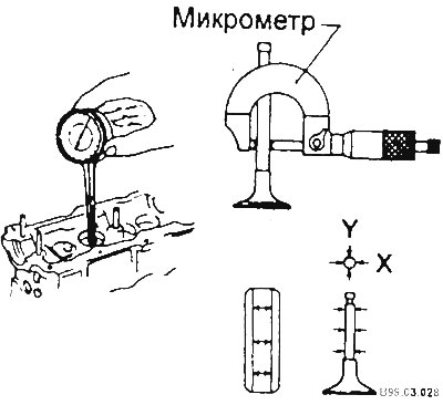
Nominal clearance for intake valves: 0.020-0.050 mm; nominal clearance for exhaust valves 0.050-0.090 mm; maximum permissible gap - 0.15 mm.
If the clearance exceeds the maximum allowable value, replace the valve or guide bushing.
Clean the mating surface of the cylinder head. Using a metal ruler and feeler gauge, check whether the flatness is within the permissible limits. The check should be performed in six directions, as shown in the figure below.
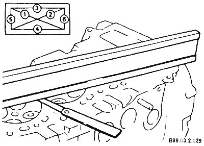
Deviation from flatness nominal - no more than 0.03 mm; maximum permissible - 0.1 mm. If the non-flatness in at least one direction exceeds the permissible limit, replace or regrind the cylinder head.
Valves
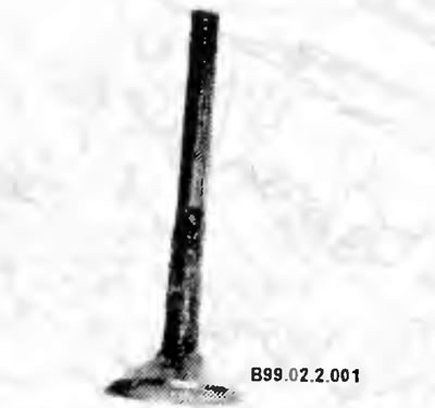
Carefully inspect each valve for uneven wear, warping, cracks, dents and burnt areas. Check the condition of the valve stem.
Turn the valve and see if it is bent. Check for dents and heavy wear on the end of the stem. The presence of any of the described damage indicates that the valves need to be ground.
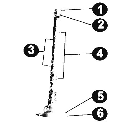
Checking valve wear at the indicated points
1 - end of valve; 2 - cracker groove; 3 - rod (least worn section); 4 - rod (the most worn section); 5 - valve surface; 6 - tap.
Measure the edge width of each valve. If the edge width of the valve is less than the value specified in the technical data, the valve should be replaced with a new one.
Valve elements
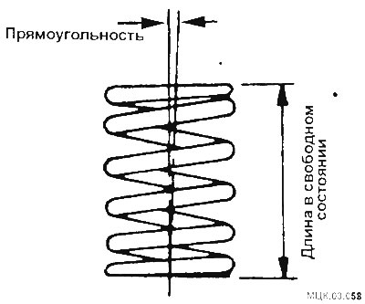
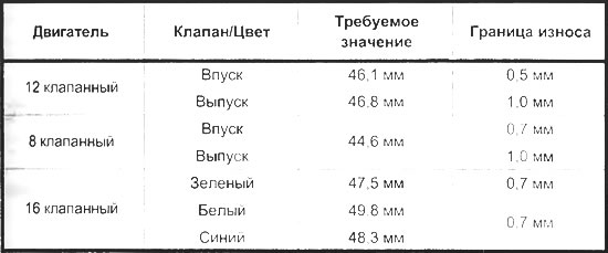
Check each valve spring at the ends for wear and dents. Measure the free length of the spring and compare the results with the reference dimensions. Springs with a free length less than the specified should be replaced. The tension of all springs should be measured with a special device before deciding whether they are suitable for further use in the rebuilt engine (springs should be taken to a workshop for this check).
Place each spring on a flat surface, check that it is level and straight. If the springs are damaged or compressed, replace all springs in the set.
Check the spring cotters for obvious wear and cracks. Any parts that are in doubt should be replaced with new ones, as if they fail while the engine is running, they can cause severe damage.
Hydraulic valve lifters
CAUTION: Hydraulic tappets must be stored in a container with oil in an upright position.
Place the hydraulic lifter in a container with clean diesel fuel.
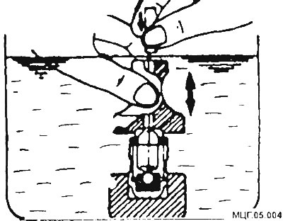
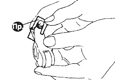
Using a special tube (for releasing air), press on the steel ball and move the piston up and down several times. The air should come out.
Remove the tube and check the condition of the hydraulic tappet - it should be in a free state. If the hydraulic tappet is compressed, then it is necessary to repeat the air removal process.
After releasing the air, install the hydraulic tappet in a special device and check the hydraulic tappet for leaks.
If necessary, replace the hydraulic lifter with a new one.
CAUTION: Do not lay the pumped hydraulic tappet on its side. Always use the special bracket when installing.
Camshaft Bearing Housings
Check the camshaft bearing housings for wear and damage.
The text of the article was taken from the website (mitsubishiman.ru)
If wear and cracks are detected, consult with specialists. If repair is not possible, a new cylinder head should be purchased, since the camshaft bearing housing and the cylinder head are processed together.