
English Русский
Български
Беларускі
Український
Српски
Hrvatski
Română
Polski
Slovenský
Magyar
Articles Bookmark Contacts Sitemap   
Company Audi Company Ford Company Hyundai Company Kia Company Mazda Company Mercedes-Benz Company Nissan
MitsubishiMan.ru


Home Colt Lancer Galant L200 Outlander Pajero Others
Galant 6 and 7 (1987-1998) Galant 5 (1983-1989, petrol)

Cylinder head — assembly (Mitsubishi Galant 5)

  • Home
  • Galant
  • 5 (1983-1989, petrol)
  • Power unit
  • Engine overhaul
  • Cylinder head — assembly
0
1. Regardless of where you repaired the cylinder head and valves, check them for cleanliness before starting assembly.

2. If you have taken the cylinder head to a workshop for repair, the valves and related parts are already installed. Begin the assembly procedure from step 8.

3. Install a new seal into each valve guide. Using a hammer and deep socket or seal installation tool, carefully press each seal into place until it seats on the guides (see illustration). Do not twist the seals during installation or they will not seat properly on the valve stems.
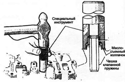


12.3. A special tool is required to install the valve stem seals (but a deep socket head can also be used) - do not hit the seals after they are seated in place


4. Starting at one end of the cylinder head, lubricate and install the first valve. Lubricate the valve stem with lithol or motor oil.

5. Place the spring seat onto the valve guide and install the spring and spring retainer (see illustration).
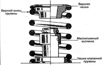


12.5 If the cylinder head is equipped with special enamel-coated valve springs, install the valve springs with the painted side away from the cylinder head, as shown


6. Compress the springs with a special tool and install the crackers in the upper groove, then slowly loosen the tool and make sure that the crackers are securely seated in place. If necessary, apply a small amount of thick grease to hold the crackers in place.

7. Repeat the procedure for the remaining valves. Make sure to install the parts in their original positions.

8. Check the height of the installed spring using a ruler with a division value of 0.5 mm or a caliper. If the head was repaired in a workshop, the height should correspond to the standard (but this does not follow automatically). The measurement is made from the upper part of the spring seat to the lower part of the plate (see the illustration). If the height is greater than that specified in the specification of this chapter, then adjusting washers must be installed under the spring for correction.
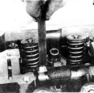


12.8. Check the height of the installed spring (distance from the top of the seat/gasket to the top of the spring


(Article reprinted from the website MITSUBISHIMAN.ru)

Caution: Under no circumstances should the installed spring height be less than the specification.


9. Using special tool MD998308, press the injector valve stem seal into place in the valve body (see illustration). Do not reuse old seals or attempt to install seals using other tools.
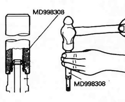


12.9. There is a special tool for replacing the oil seal of the injector valve


10. When installing the valve into the housing, apply engine oil to the valve stem. Be careful not to damage the sealing lips of the valve stem. The injection valve stem must move freely in the housing.

11. Compress the spring with special tool MD998309 and install it together with the valve spring retainer. Install the retainer lock in place. Do not damage the valve stem seal with the bottom of the retainer.

12. Install the new sealing ring into the groove of the injector valve body and apply a thin layer of engine oil to it (see illustration). Also apply oil to the threads and seat.
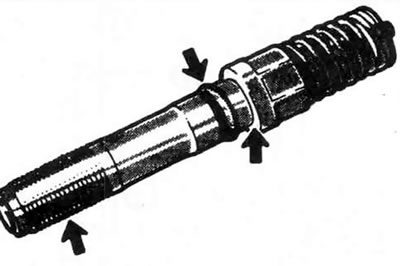


12.12. When installing the injection valve, use new sealing rings, which are lubricated with engine oil along with the threads and thrust surface


13. Install the injection valves in place and tighten them to the required torque.

14. Apply molybdenum grease to the surfaces of the valve rocker arms, camshaft and valve rocker shafts, then install the camshaft, valve rocker arms and shafts (see part A).
This article is available at: russian, bulgarian, belarusian, ukrainian, serbian, croatian, romanian, polish, slovak, hungarian
This article was reviewed by: Vladimir Glazunov
Share with friends:
◀ Previous
Galant 5: Engine overhaul
Next ▶

Valves — Maintenance
Cylinder head — cleaning and inspection
Cylinder head — disassembly
Engine overhaul — disassembly sequence
Engine assembly options
Pistons/Connecting Rods — Removal
Crankshaft — extraction
Cylinder Block — Cleaning
Cylinder Block — Check
Cylinder honing
Similar materials for other Mitsubishi models

➤ Cylinder Head Cover — Removal and Installation (All Engines) Mitsubishi Colt 4 and 5 (1991-2003)
➤ Cylinder head of a gasoline engine — device Mitsubishi Lancer 3 and 5 (1984-1992)
➤ Removal the cylinder head Mitsubishi L200 4 (2005-2014, diesel)
➤ Removal and installation the cylinder head (4G64, 4G69) Mitsubishi Outlander 1 (2003-2008)
➤ Cylinder Head Cover — Removal and Installation Mitsubishi Pajero 1 and 2 (1982-1999)
➤ SOHC Engine Cylinder Head Gasket Mitsubishi Carisma (1995-2004)
Link in different formats to this article
Comments and feedback from visitors
No comments yet


Add up two numbers 17 + 13


Galant 6 and 7 (1987-1998) 
  • General information
  • Introduction to guide
  • User manual
  • Driving and operation
  • Maintenance
  • Power unit
  • Dismantling the engine
  • Engine overhaul
  • Cooling and heating
  • Power and exhaust systems
  • Engine electrical equipment
  • Engine management systems
  • Transmission
  • Mechanical gearbox
  • Automatic gearbox
  • Clutch
  • Drive shafts and transfer case
  • Chassis and running gear
  • Brake system
  • Car suspension
  • Steering
  • Body and interior
  • Exterior (external elements)
  • Interior (internal elements)
  • Doors, locks and windows
  • Electrical equipment
  • Equipment and devices
  • Wiring diagrams Galant
  • Wiring diagrams Mirage
  • Wiring diagrams Diamante
Galant 5 (1983-1989, petrol) 
  • General information
  • Troubleshooting
  • Maintenance
  • Power unit
  • Engine repair
  • Engine overhaul
  • Cooling and heating
  • Fuel and exhaust system
  • Engine electrical equipment
  • Reducing exhaust toxicity
  • Transmission
  • Manual gearbox
  • Automatic gearbox
  • Clutch and drive shafts
  • Chassis and running gear
  • Brake system
  • Car suspension
  • Steering
  • Body and interior
  • Exterior (external elements)
  • Interior (internal elements)
  • Doors, locks and windows
  • Electrical equipment
  • Equipment and devices
  • Electrical diagrams
MitsubishiMan.ru © 2018–2026 • Mobile version • Articles about Mitsubishi • Contacts • Sitemap: EN BG BY UA RS HR RO PL SK HU • Site search • Bookmark
Colt 2 and 3 (1983-1993) · Colt 4 and 5 (1991-2003) · Colt 5 (1995-2003) · Lancer 3 and 5 (1984-1992) · Lancer 9 (2000-2007) · Galant 5 (1983-1989) · Galant 6 and 7 (1987-1998) · L200 4 (2005-2014) · Outlander 1 (2003-2008) · Pajero 1 and 2 (1982-1999) · Pajero 4 (2006-2021) · Carisma (1995-2004) · Space Star (1998-2005) ·
This resource sets cookies 🍪 to avoid bothering you with repeated data entry.