
Selection of liners of main bearings of a cranked shaft
Note. If the liner needs to be replaced, select and install the correct size liner.
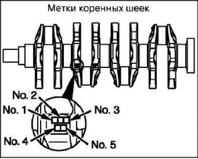
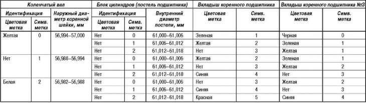
If the crankshaft is supplied as a replacement part, identify the color or symbol marks on the crankshaft main journals that are stamped in the location shown in the figure. If identification of the crankshaft by marks is not possible (no tags), then measure the diameter of each crankshaft main journal.
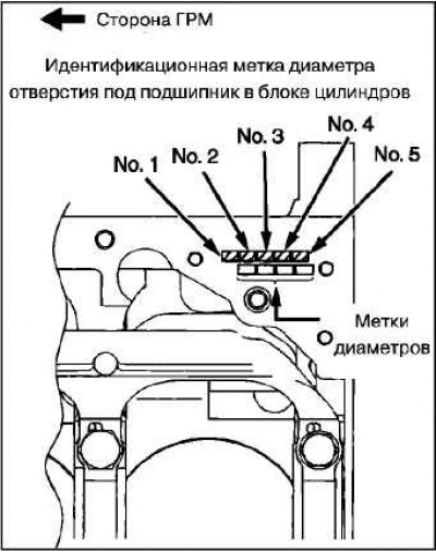
Determine the character identification marks on the cylinder block (size groups of bore diameters for main bearings), which are stamped at the location shown in the figure, from the front to the back of the unit. The mark for the neck No. 1 is located on the side of the front of the engine (from the timing belt side).
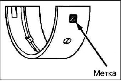
The crankshaft main bearing shells are identified by color and/or symbol labels, which are located as shown in the figure.
 |  |
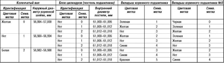
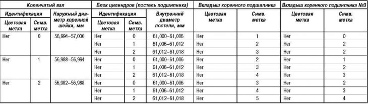
According to certain marks on the crankshaft (or the results of measurements of the main journals of the shaft) and identification marks on the cylinder block, select the correct main bearing shells from the table below.
Installing the crankshaft main bearing shells
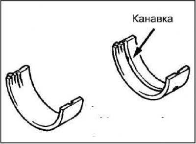
Install the upper crankshaft main bearing into the cylinder block. The upper crankshaft main bearing has a groove for lubrication.
Install the lower crankshaft main bearing into the crankshaft seat.
Install the thrust washers on both sides of the No. 3 main bearing with the grooves facing out (to the cheek of the counterweight).
Installing the crankshaft bed
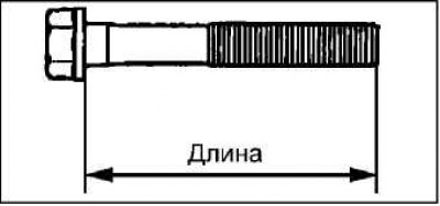
Before installing the fastening bolts, check that the length of the rod for each bolt does not exceed the maximum allowable value. If the limit value is exceeded, replace the bolt.
Limit value (no more): 71.1 mm.
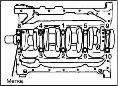
Install the crankshaft bed on the cylinder block so that the arrow on it is located on the side of the timing belt.
Apply engine oil to the threads of the bolts and under their heads.
Tighten the crankshaft bed mounting bolts to the specified tightening torque in the sequence shown in the figure.
Tightening torque: 25±2 Nm.
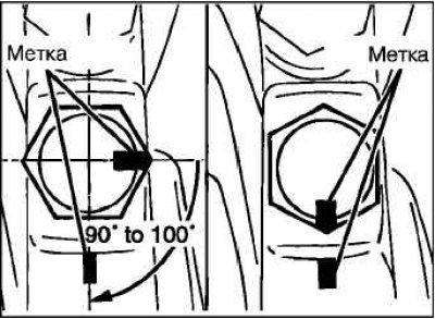
Apply a color mark to the head of each bolt and tighten the crankshaft bed mounting bolts (bearing caps) at an angle of 90° (1/4 turn) in the above sequence.
Attention! If the bolt is turned at an angle of less than 90°, then the crankshaft bed will be insufficiently fastened.
Attention! If the bolt is turned more than 100°, loosen the bolt and repeat the tightening procedure.
Make sure the crankshaft rotates smoothly.
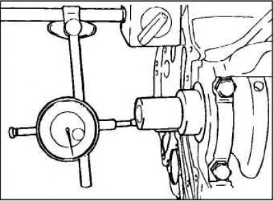
Check crankshaft end play.
Selection table for crankshaft main bearing shells (Engine 4G63-7)
Selection table for crankshaft main bearing shells (Engine 4G64)
Selection table for crankshaft main bearing shells (Engine 4G69)
Axial clearance of the crankshaft
Nominal:
- Engine 4G63-7: 0.05–0.25 mm.
- 4G64 engine: 0.05–0.18 mm.
- 4G69 engine: 0.05–0.25 mm.
Maximum allowable:
- Engine 4G63-7: 0.25 mm.
- 4G64 engine: 0.25 mm.
- 4G69 engine: 0.40 mm.
Installation of a back epiploon of a cranked shaft
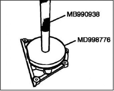
Using a special mandrel, install a new oil seal into its housing.
Installing the crankshaft rear oil seal housing
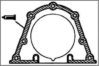
Apply the specified sealant to the stuffing box at the locations shown in the illustration.
MITSUBISHI GENUINE Part No. MD 970389, Three Bond 1207F or equivalent.
Apply a thin coat of engine oil to the lip of the oil seal around its entire circumference.
Note. Install the gland housing within 15 minutes of applying the sealant.
After installation, do not allow oil and coolant to come into contact with sealant-coated surfaces of the stuffing box.
Install the oil seal housing on the cylinder block and tighten the bolts of its fastening to the nominal torque.
Tightening torque: 11±1 Nm.