
Installing the oil scraper ring
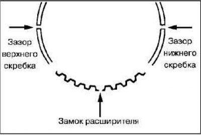
Install the oil scraper ring expander into the ring groove in the piston.
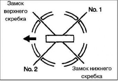
Note. Make sure that the gaps in the locks of the scrapers and expander are located as shown in the figure.
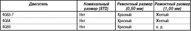
New details (expander and scrapers) are color-coded according to their size (see corresponding table).
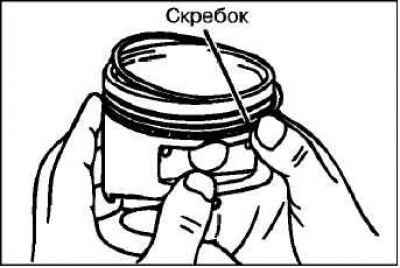
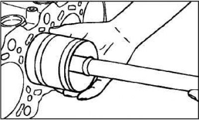
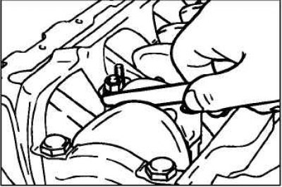
Install the top oil ring scraper. To install the top scraper, first install one end of the scraper into the piston groove, then slide the rest of the scraper with your finger as shown in the figure.
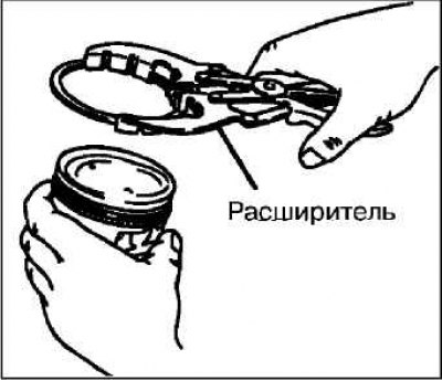
Attention! Do not use a piston ring expander. Unlike other parts of the piston rings, the scraper of the oil scraper ring can break when it is expanded with an expander.
Install the lower oil ring scraper in the same way as the upper one.
Check the correct installation of the oil scraper ring, which consists of three parts. When the oil scraper ring is correctly installed, it should rotate smoothly in any direction.
Table of color marks for oil scraper ring sizes
Installation of compression rings No. 1 and No. 2
 | 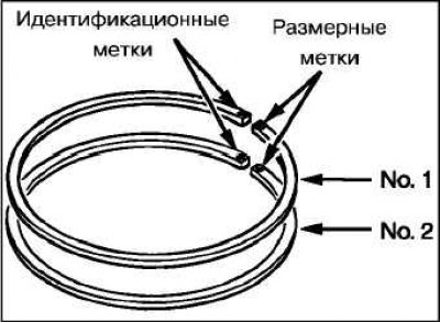 |
Use a compression ring expander to install compression rings #1 and #2 with the identification marking facing up.
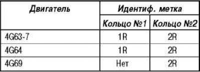
Note. Each compression ring has a size and identification marks stamped on the ends of the ring. When installing, position the ring so that the mark is on top (see table).
Selection of connecting rod bearing shells
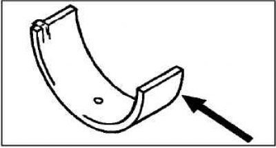 | 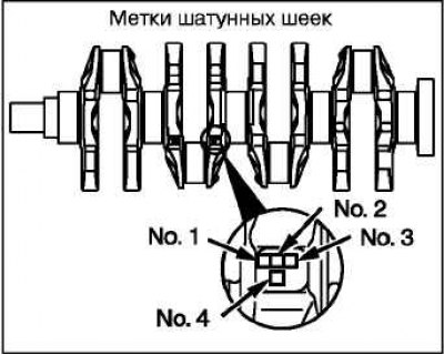 |
When replacing connecting rod bearing shells, select them according to the tables below in accordance with the size group (character or color labels) crankshaft and size group (character or color labels) connecting rod bearing shells.
Nominal connecting rod bore diameter: 48.000 - 48.015 mm.
Chart for selection of connecting rod bearing shells (engine 4G63-7)
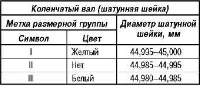
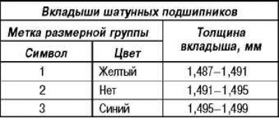
Chart for selection of connecting rod bearing shells (4G64 engine)
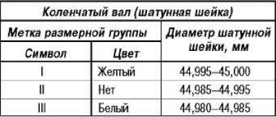
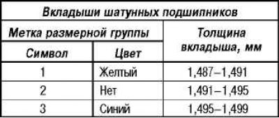
Chart for selection of connecting rod bearing shells (4G69 engine)
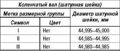

Attention! The size group mark of the crankshaft journal is applied only to the part supplied as a spare part.
Piston and connecting rod assembly installation
Lubricate the surfaces of the piston and piston rings with a thin layer of engine oil.
Position the locks of the compression rings and the oil scraper ring (expander and scrapers), as it shown on the picture.
Turn the crankshaft so that the connecting rod journal of the shaft is in the middle of the cylinder bore.
Use suitable protectors on the connecting rod bolt threads before installing the piston and connecting rod assembly into the cylinder bore. This will avoid damage to the working area of the crankshaft journals.
Using a ring compressor, install the piston and connecting rod assembly into the cylinder bore of the block.
Attention! The piston and connecting rod assembly must be installed in the cylinder block with the mark on the piston facing the front of the engine (timing flint).
Installing the connecting rod cap and checking the axial clearance of the lower head of the connecting rod
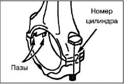
Align the appropriate caps with the appropriate connecting rods, taking into account the markings made (cylinder number) and the method of fixing the liners (slots for inserts). If a new connecting rod without alignment marks is installed, then position the grooves for fixing the liners on the connecting rod and cover on one side.
Use a feeler gauge to measure the bottom end clearance of the connecting rod.
- Nominal axial clearance: 0.10–0.25 mm.
- Maximum allowable axial clearance: 0.40 mm.
Tightening of nuts of fastening of a cover of a rod
The connecting rod cap bolt and nut are tightened «yield strength». Before installing the bolt, make sure that the thread of the bolt/nut is not deformed. The presence of deformation of the bolt-nut connection is checked by manually screwing the nut onto the bolt until the end of the thread. If the nut is difficult to screw onto the bolt by hand, the bolt thread is deformed and the bolt must be replaced.
Before installing the nut, coat the threaded parts of the nut and bolt with a thin layer of engine oil.
Screw the nuts onto the appropriate bolts by hand. Then tighten each nut individually to make sure the connecting rod cap is properly seated.
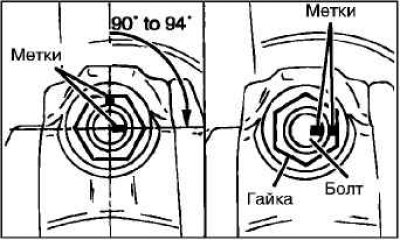
Alternately tighten the cap nuts to the specified torque.
- Tightening torque: 20±2 Nm.
- Tighten the nuts securing the covers at an angle of 90–94°.
Attention! If the nut is turned at an angle of less than 90°, then the tightening of the cover fastening nuts will be insufficient.
Attention! If the nut is turned more than 94°, loosen the nut and repeat the tightening procedure.