



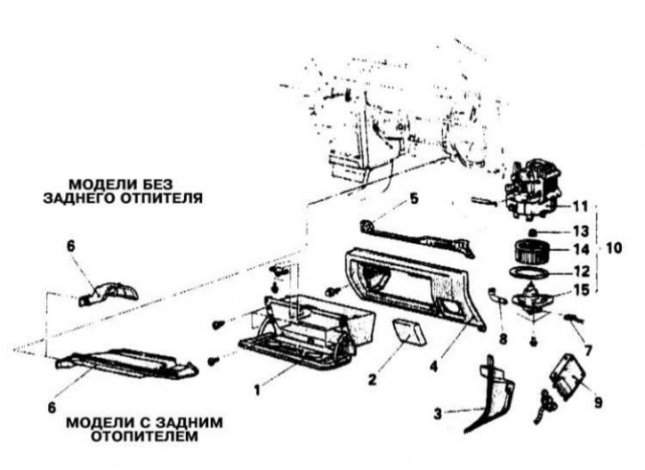
Heater fan installation details for Mirage models 1990÷1992.
1 - Glove box; 2 - Loudspeaker grille; 3 - Front door sill trim (right-hand drive models); 4 - Knee support (right-hand drive models); 5 - Mounting frame of the glove box; 6 - Elbow (models without rear heater)/flow (models with rear heater) air duct; 7 - Fan drive motor wiring connector; 8 - Hose; 9 - Control unit of the distributed injection system (MPI); 10 - Fan assembly; 11 - Fan shroud; 12 - Sealing gasket; 13 - Impeller mounting nut; 14 - Impeller; 15 - Drive electric motor
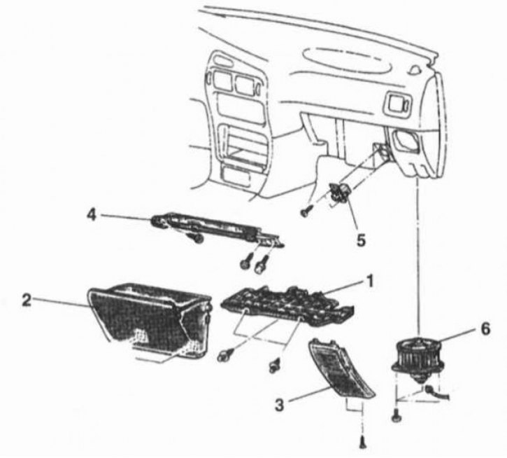
Heater fan installation details for Mirage models 1993÷1996.
1 - Lower trim section; 2 - Glove box; 3 - Corner trim panel; 4 - Glove box mounting frame; 5 - Resistive assembly; 6 - Assembling the heater fan with the drive motor
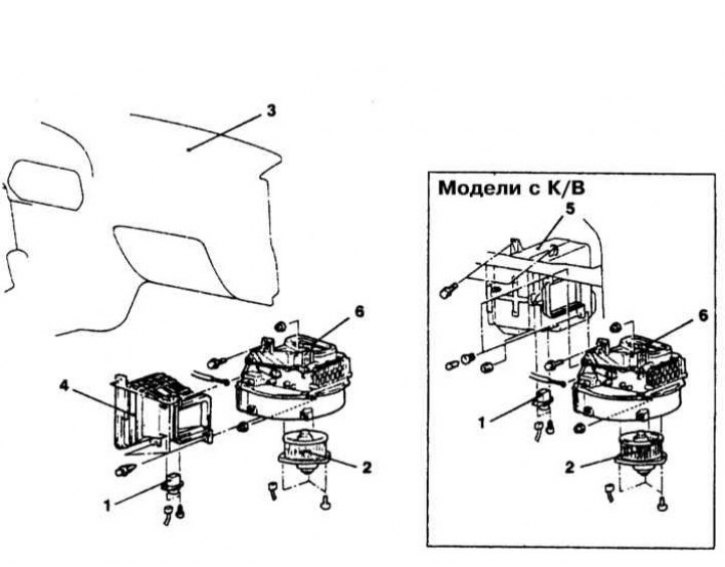
Heater fan installation details for Mirage models 1997÷2000.
1 - Resistive assembly; 2 - Assembly of the heater fan with a drive electric motor; 3 - Instrument panel; 4 - Connecting sleeve (models without K/V); 5 - Evaporator (models with A/C); 6 - Fan shroud
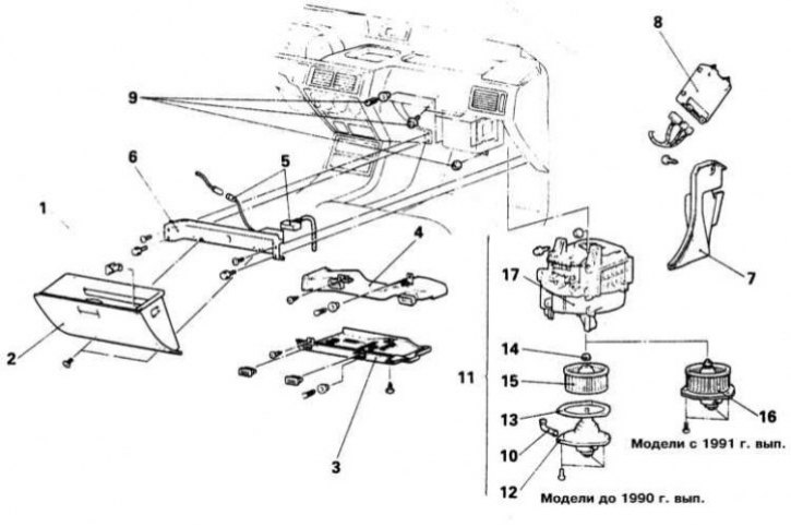
Heater fan installation details for Galant models 1990÷1993.
1 - Thrust retainer; 2 - Glove box; 3 - Lower trim panel; 4 - Air supply hose to the foot wells; 5 - MFI control relay and glove compartment light switch wiring connectors; 6 - Glove box mounting frame; 7 - Front door sill trim; 8 - Engine control module; 9 - Evaporator fasteners (models with A/C)/air duct fasteners (models without A/C); 10 - Hose; 11 - Assembling the fan with the casing; 12 - Drive electric motor; 13 - Sealing gasket; 14 - Impeller mounting nut; 15 - Impeller; 16 - Assembling the fan with the drive motor; 17 - Fan shroud
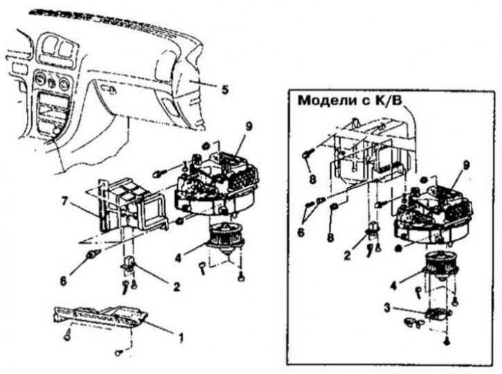
Heater fan installation details for Galant models 1994÷1998.
1 - Lower trim panel; 2 - Resistive assembly; 3 - ECM compressor K/V (models with K/V); 4 - Assembling the heater fan; 5 - Instrument panel; 6 - Retainer; 7 - Connecting sleeve (models without K/V); 8 - Evaporator fastening (models with A/C); 9 - Fan shroud
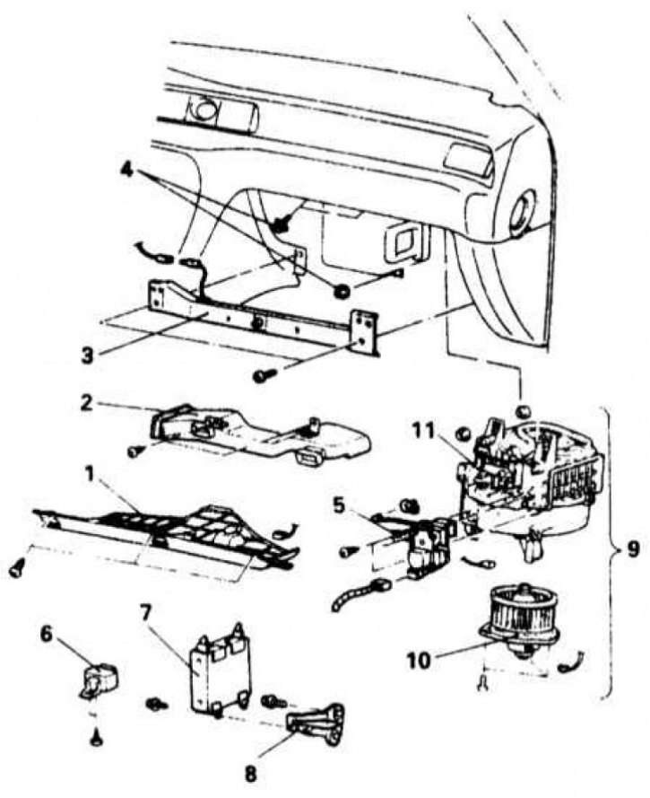
Details of installation of heater fan on Diamante models 1992÷1996.
1 - Lower trim panel; 2 - Air supply hose to the foot wells; 3 - Mounting frame of the glove box; 4 - Evaporator fastener; 5 - Assembling the circulation mode switching motor; 6 - MFI control relay; 7 - MFI control unit; 8 - Right lower instrument panel bracket; 9 - Assembling the heater fan with the casing; 10 - Assembling the heater fan; 11 - Fan shroud
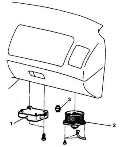
Details of installation of heater fan on Diamante models 1997÷2000.
1 - Drive belt lock controller K/V; 2 - Assembling the heater fan; 3 - High-speed heater fan relay
Warning! The vehicles covered in this manual are equipped with the Supplemental Restraint System (SRS), better known as the airbag. Before performing any work near the airbag assembly or steering column, always disable the system to avoid injury from accidental deployment - disconnect the negative battery cable first, then the positive cable, and wait at least two minutes before servicing components located near the directional overload sensors (see Chapter On-board electrical equipment). The insulation and connectors of the SRS circuit wiring are painted bright yellow. Do not connect any diagnostic equipment to this circuit!
Mirage Models
Removal
1. Heater fan installation details on Mirage models are shown in the illustrations.
2. Disconnect the negative cable from the battery.
Warning! If the car stereo system is equipped with a security code, make sure you have the correct combination to activate the audio system before disconnecting the battery!
3. Remove the right section of the lower instrument panel trim (see Chapter Body).
4. Remove the glove box assembly and its mounting frame (see Chapter Body).
5. Disconnect the electrical wiring from the heater fan drive motor.
6. Disconnect and remove the resistive assembly.
7. Disconnect the drive motor ventilation tube.
8. Remove the mounting bolts and drive motor block. Replace the fan impeller if necessary.
Installation
1. Install the drive motor assembly in its original place and screw in the mounting bolts.
2. Connect the electrical wiring to the motor.
3. Connect the ventilation tube.
Galant models 1993÷1993.
Removal
1. The heater fan installation details on Galant models produced in 1990÷1993 are shown in the illustration.
2. Disconnect the negative cable from the battery.
Warning! If the car stereo system is equipped with a security code, make sure you have the correct combination to activate the audio system before disconnecting the battery!
3. Remove the glove box retainer.
4. Open the glove box cover all the way and remove the lower assembly mounting screws. Remove the glove box.
5. Remove the right section of the lower instrument panel trim (see Chapter Body).
Note: Please note that some of the mounting screws are covered by decorative caps that must be removed first.
6. Remove the air supply hose to the front passenger footwell.
7. Disconnect the 10-pin connector on the rear of the glove box mounting frame. Disconnect the wiring from the glove box light switch sensor (also mounted on the mounting frame).
8. Remove the four mounting bolts and remove the glove box mounting frame.
9. Disconnect the small air hose running from the fan motor to the fan shroud.
10. Disconnect the electrical wiring from the drive motor.
11. Remove the three mounting bolts and remove the fan assembly from the casing. If necessary, loosen the nut and remove the impeller.
Installation
1. Carefully inspect the casing from the inside, removing any debris or foreign objects that could interfere with the rotation of the impeller.
2. Assess the condition of the sealing gasket and replace it if necessary.
3. Install the heater fan in its regular place. Screw in and tighten the mounting bolts.
4. Connect the ventilation hose and electrical wiring to the drive motor.
5. Install the glove box mounting frame and connect both electrical connectors (10-pin and 1-pin) to it.
6. Install the air duct.
7. Install the lower instrument panel trim section - ensure that it is installed correctly and that all fasteners are securely latched.
8. Install the glove box with the stop latch.
9. Connect the negative cable to the battery.
Galant models 1994÷2000.
Removal
1. The heater fan installation details on Galant models produced in 1994÷2000 are shown in the illustrations.
2. Disconnect the negative cable from the battery.
Warning! If the car stereo system is equipped with a security code, make sure you have the correct combination to activate the audio system before disconnecting the battery!
3. Remove the three mounting screws and remove the lower section of the instrument panel trim (see Chapter Body).
4. On models equipped with air conditioning, remove the compressor module.
5. Disconnect the electrical wiring from the heater fan drive motor.
6. Remove the three mounting screws and remove the fan assembly from the shroud.
Installation
1. Carefully inspect the casing from the inside, removing any debris or foreign objects that could interfere with the rotation of the impeller.
2. Install the heater fan in its regular place. Screw in and tighten the mounting bolts.
3. Connect the electrical wiring to the drive motor.
4. If the vehicle is equipped accordingly, install the A/C compressor module.
5. Install the lower instrument panel trim section - ensure that it is installed correctly and that all fasteners are securely latched.
6. Connect the negative cable to the battery.
Diamante Models
Removal
1. The heater fan installation details on Diamante models are shown in the illustrations.
2. Disable the airbags (see Chapter On-board electrical equipment).
3. Remove the right section of the lower instrument panel trim and the air duct sleeve.
4. Remove the glove box lock striker, glove box assembly and its outer casing. Remove the screw located under the assembly.
5. Remove the evaporator casing fasteners.
6. Remove the circulation mode switching motor assembly.
7. Remove the PCM, support bracket and MFI control relay.
8. Remove the right lower instrument panel bracket.
9. Disconnect the molded hose from the fan assembly.
10. Remove the fan assembly.
11. If necessary, loosen the fastening nut and remove the impeller.
Installation
1. Check the drive pump shaft for signs of bending. Assess the condition of the sealing gasket. Thoroughly clean all assembly parts, blow out the air duct.
2. Fasten the fan impeller to the drive pump shaft.
3. Install the assembly in its regular place.
4. Connect the cast hose and electrical wiring to the motor.
5. Screw in the evaporator casing mounting bolt.
6. Install the right lower instrument panel bracket.
7. Install the PCM, support bracket and MFI control relay.
8. Install the circulation mode switching damper motor assembly.
9. Install the screw located under the glove box assembly, then install the glove box - proceed in the reverse order of removing the components.
10. Install the lower instrument panel trim section/air duct sleeve.
11. Connect the negative cable to the battery. Check the correct operation of the automatic air conditioning system (climate control).