



Contents: Removal ⤓ Installation ⤓
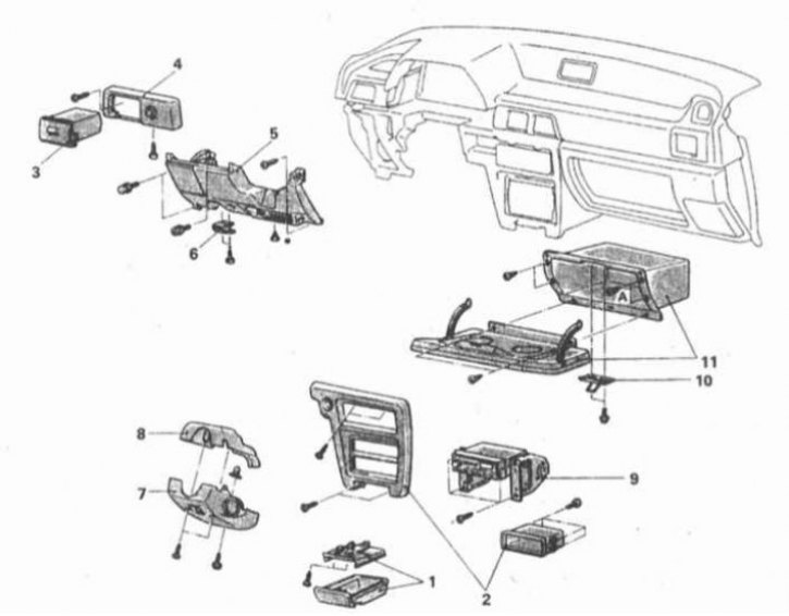
Instrument cluster installation details for Mirage models up to 1992 (1 of 2)
1 - Ashtray; 2 - Central trim section; 3 - Pocket for storing sunglasses; 4 - Side trim panel; 5 - Knee support; 6 - Hood lock release handle; 7 - Lower section of steering column cover; 8 - Upper section of steering column cover; 9 - Radio receiver; 10 - Drummer; 11 - Glove box
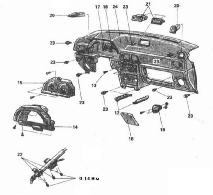
Instrument cluster installation details for Mirage models up to 1992 (2 of 2)
12 - Lower cover of the trim panel; 13 - Heater control assembly mounting screw; 14 - Instrument cluster trim panel; 15 - Instrument cluster; 16 - Speedometer drive cable tip; 17 - Instrument cluster wiring connectors; 18 - Decorative speaker cover; 19 - Loudspeaker speaker; 20 - Side air duct deflector grille; 21 - Clock/plug; 22 - Steering shaft mounting bolt/nut; 23 - Instrument panel mounting bolts; 24 - Assembling the instrument panel
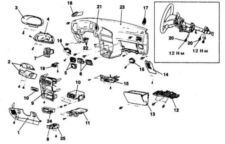
Details of installation of the instrument panel on Mirage models 1993÷1996.
1 - Knee support; 2 - Steering column cover sections; 3 - Instrument panel trim; 4 - Instrument cluster; 5 - Electric rear view mirror switch/plug; 6 - Coin holder/rear window wiper/washer control switch; 7 - Air duct deflector; 8 - Ashtray; 9 - Central air duct deflector; 10 - Radio; 11 - Cup holder; 12 - Trim panel (1993 models); 13 - Glove box; 14 - Side trim panel; 15 - Assembly of heater operation control; 16 - Loudspeaker; 17 - Right air duct deflector grille; 18 - Left air duct deflector grille; 19 - Bonnet lock release handle; 20 - Steering column mounting bolts; 21 - Speedometer drive cable tip; 22 - Electrical wiring connector; 23 - Instrument panel; 24 - Ashtray panel; 25 - Ashtray bracket
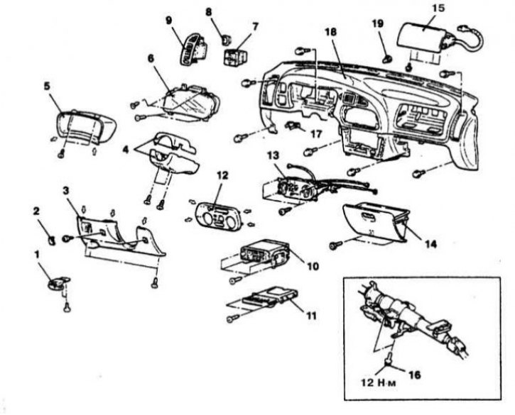
Instrument cluster installation details for Mirage models from 1997 onwards.
1 - Hood release handle; 2 - Knee support mounting screw plug; 3 - Assembling the knee support; 4 - Steering column cover sections; 5 - Instrument panel trim; 6 - Instrument cluster; 7 - Door mirror electric switch/plug; 8 - Main Cruise Control Switch/Fog Light Switch/Blind Plug; 9 - Side air duct deflector for interior ventilation/heating systems; 10 - Radio; 11 - Cup holder; 12 - Heater control panel trim; 13 - Assembly of heater operation control; 14 - Glove box; 15 - Front passenger SRS module; 16 - Steering column mounting bolt; 17 - Electrical wiring connector; 18 - Instrument panel; 19 - Bushing
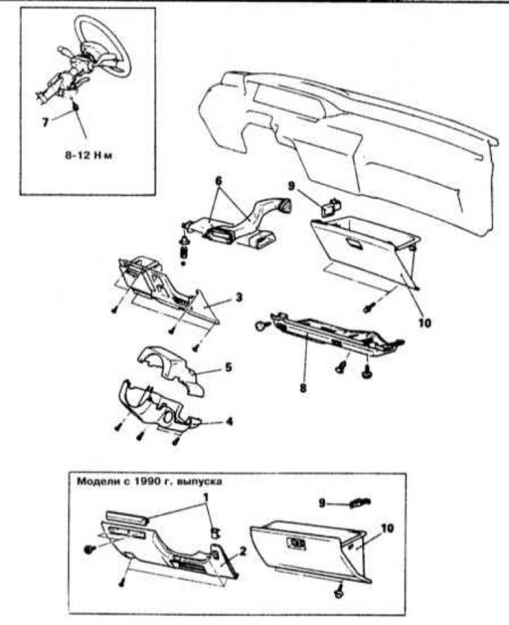
Galant 1993-Pre-Dashboard Installation Details (1 of 2)
1 - Plug; 2 - Knee support; 3 - Finishing panel; 4 - Lower section of steering column cover; 5 - Upper section of steering column cover; 6 - Air duct; 7 - Steering column angle adjustment bolt; 8 - Finishing panel; 9 - Stop; 10 - Glove box
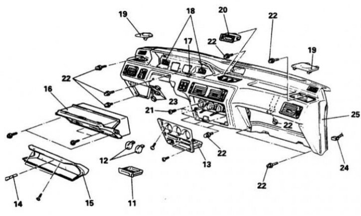
Galant 1993-Pre-Dashboard Installation Details (2 of 2)
11 - Ashtray; 12 - Handles; 13 - Assembly of heater operation control; 14 - Current mileage counter reset button; 15 - Instrument panel trim; 16 - Instrument cluster; 17 - Speedometer drive cable tip; 18 - Instrument cluster wiring connectors; 19 - Decorative speaker covers; 20 - Hours; 21 - Heater control assembly mounting screws; 22 - Instrument panel mounting bolts; 23 - Contact connectors for connecting body and instrument wiring harnesses; junction block; 24 - MPI control relay connector; 25 - Instrument panel
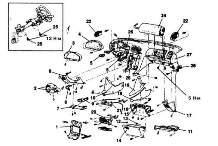
Details of installation of the instrument panel on Galant models 1994÷1998.
1 - Console section of the instrument panel trim; 2 - Steering column cover sections; 3 - Instrument panel trim; 4 - Instrument cluster; 5 - Instrument cluster switch; 6 - Bonnet lock release handle; 7 - Air supply hose to the foot wells; 8 - Finishing panel; 9 - Air duct B at knee level; 10 - Side cover B; 11 - Finishing panel; 12 - Stop; 13 - Latch; 14 - Glove box; 15 - Striker of the glove compartment lock; 16 - Glove compartment lid; 17 - Finishing panel; 18 - Side cover A; 19 - Side cover A; 20 - Radio with cup holder; 21 - Assembly of heater operation control; 22 - Side air duct deflector; 23 - Cold air bypass damper lever; 24 - Front passenger SRS module; 25 - Steering column mounting bolts; 26 - Electrical wiring connector; 27 - Instrument panel
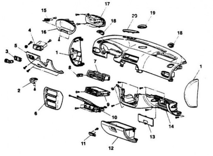
Galant 1999 and Later Instrument Cluster Installation Details (1 of 2)
1 - Side trim panels; 2 - Hood release handle; 3 - Switch panel; 4 - Contact connector holder; 5 - Finishing panel; 6 - Console section of the instrument panel trim; 7 - Central air duct deflector; 8 - Hazard warning switch; 9 - Radio; 10 - Assembly of heater control; 11 - Striker of the glove compartment lock; 12 - Glove box; 13 - Finishing panel; 14 - Finishing section; 15 - Rheostat; 16 - Instrument panel trim; 17 - Instrument cluster; 18 - Side air duct deflector; 19 - Decorative loudspeaker grille; 20 - Finishing panel
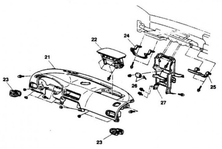
Instrument cluster installation details for Galant models since 1999 (2 of 2)
21 - Instrument panel; 22 - Front passenger SRS module; 23 - Side air duct deflector; 24 - Knee support; 25 - Knee support; 26 - ECU of the cruise control; 27 - Central reinforcing frame of the instrument panel
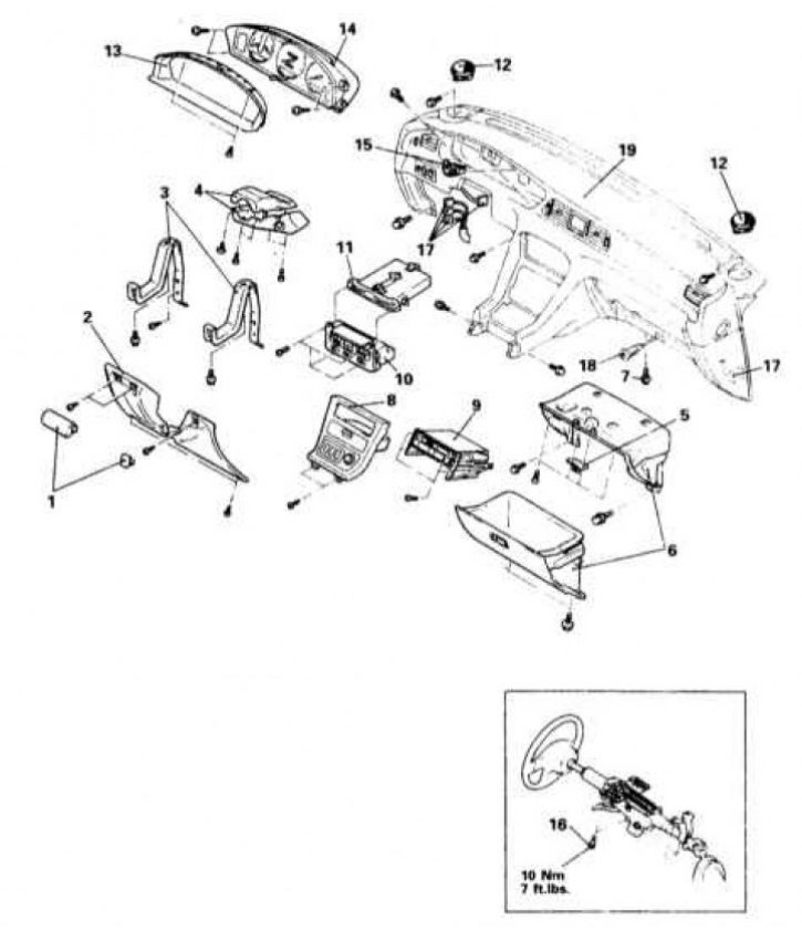
Details of installation of the instrument panel on Diamante models 1992÷1996.
1 - Plugs; 2 - Knee support; 3 - Knee support mounting brackets; 4 - Steering column cover sections; 5 - Striker of the glove compartment lock; 6 - Assembling the glove box; 7 - Trim panel mounting screw; 8 - Console section of the instrument panel trim; 9 - Radio; 10 - Assembly of heater control; 11 - Cup holder; 12 - Loudspeaker; 13 - Instrument panel trim; 14 - Instrument cluster; 15 - Speedometer drive cable tip; 16 - Steering column mounting bolts; 17 - Electrical wiring connector; 18 - Instrument lighting switch; 19 - Instrument panel
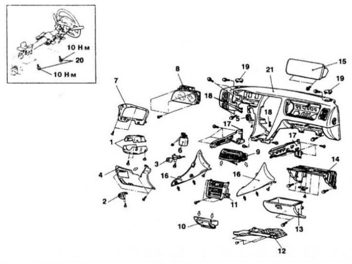
Details of installation of the instrument panel on Diamante models from 1997.
1 - Steering column cover sections; 2 - Hood release handle; 3 - Parking brake release handle; 4 - Finishing panel; 5 - Ignition switch trim; 6 - ECU control devices; 7 - Instrument panel trim; 8 - Instrument cluster; 9 - Central air duct deflector; 10 - Ashtray; 11 - Radio and heater control panel; 12 - Finishing panel; 13 - Glove box; 14 - Glove box casing; 15 - Front passenger SRS module; 16 - Finishing panel; 17 - Carpet pressure bars; 18 - Electrical wiring connector; 19 - Plug; 20 - Steering column mounting bolt; 21 - Instrument panel
Attention! To secure the instrument panel, various types of fasteners are used, each of which must be installed strictly in its original place during assembly.
Removal
1. The details of the instrument panel installation on different models are shown in the illustrations.
2. Disconnect the negative cable from the battery.
Warning! If the car stereo system is equipped with a security code, make sure you have the correct combination to activate the audio system before disconnecting the battery!
3. Remove the center console floor section(s).
4. Remove the plugs, unscrew the mounting screws and remove the knee support assembly.
5. Release the retainer and remove the hood latch release handle.
6. Remove the upper and lower sections of the steering column cover.
7. Remove the mounting screws and remove the instrument panel trim - if necessary, disconnect the corresponding electrical wiring.
8. Remove the mounting screws and remove the instrument cluster.
Note: On some models, the cluster assembly will first need to be released from the instrument panel and the wiring to the back of the cluster disconnected.
9. If equipped, disconnect the speedometer drive cable from the transmission. Pull the cable slightly into the passenger compartment by turning the end left or right, disconnect the cable from the instrument cluster.
10. Remove the radio trim panel.
11. Release the latches and remove the radio from the instrument panel. Disconnect the electrical wiring and antenna cable from the receiver and remove the assembly.
12. Remove the central ventilation/heating deflector assembly.
13. If equipped, remove the mounting screws and handles from the controls mounted in the center section of the instrument panel.
14. Pull the latches towards you and remove the glove box.
15. Remove the right and left speaker covers. Disconnect the wiring and remove the speaker drivers.
16. Loosen the mounting screws and release the heater control assembly from the instrument panel. Disconnect the electrical wiring and drive cables from the assembly and remove it from the vehicle.
17. Remove the air ducts of the interior ventilation/heating systems - try to remember the order of installation of the sleeves.
18. Remove the mounting bolts and lower the steering column, resting the steering wheel against the driver's seat cushion - make sure that the corresponding electrical wiring harnesses are not stretched.
19. Remove the instrument panel mounting bolts, mark and disconnect the electrical wiring.
20. Remove the instrument panel assembly from the vehicle and, if necessary, remove any removable components from it.
Installation
1. Install the instrument panel in its original place and restore the original wiring connection - make sure the harnesses are connected correctly. Make sure that no wires are pinched, then screw in and tighten the mounting bolts.
2. Further installation is carried out in the reverse order of dismantling the components.