



Contents: Removal ⤓ Installation ⤓
Removal
To remove the heater control panel assembly and air conditioner switch, perform the following steps.
1. Disconnect the cable from the negative terminal of the battery.
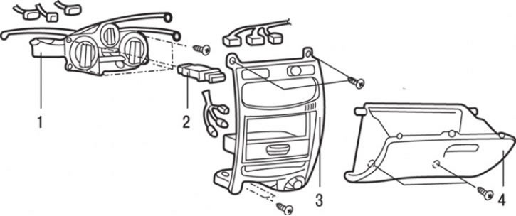
Fig. 18.3. Heater control panel assembly and air conditioner switch: 1 – heater control unit; 2 – air conditioner switch; 3 – center console panel; 4 – storage box
2. Using a screwdriver blade as a lever, release the clips and remove panel 3 (Fig. 18.3) of the center console.
3. Loosen the screws and remove the glove box 4.
4. Loosen the screws, disconnect the cables and electrical connectors and remove the heater control unit 1.
5. Using a screwdriver blade as a lever, remove air conditioner switch 2.
(Information copied from the website mitsubishiman)
Installation
Installation is carried out in the reverse order of removal, taking into account the following.
1. Set the heater temperature control knob to the "MAX HOT" position.
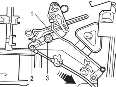
Fig. 18.4. Position of the temperature control handles and the air mixing flap drive during installation: 1 – air mixing flap drive lever; 2 – position "MAX NOT" (warm); 3 – position "MAX COOL" (cold)
2. Set the air mixing flap drive handle to the "MAX HOT" position, as shown in Fig. 18.4, and then attach the rod to the lever axle.
3. Move the rod in the direction of the arrow shown in Fig. 18.4 to remove the play, and then secure it with the clamp.
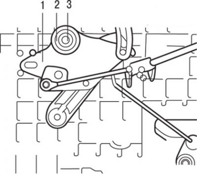
Fig. 18.5. Position of the air supply flap drive handle and lever: 1 – air supply flap drive lever; 2 – position "DEF" (window blowing); 3 – position "FACE" (face blowing)
4. Set the air supply flap drive handle of the heater control unit to the "DEF" position (Fig. 18.5).
5. Set the air intake flap actuator lever to the "DEF" position and then attach the rod to the lever shaft.
6. Move the rod in the direction of the arrow shown in Fig. 18.5 to remove the play, and then secure it with the clamp.
7. Set the air intake control knob on the heater control panel to the "INSIDE" position.
8. Set the heater air inlet control drive lever to the "INSIDE" position and then attach the rod to the lever axle.
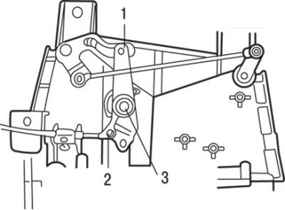
Fig. 18.6. Position of the handle and the air intake control drive lever: 1 – air supply and exhaust control flap drive link; 2 – position "INSIDE" (internal recirculation); 3 – position of outside air intake
9. Move the rod in the direction of the arrow shown in Fig. 18.6 to remove the play, and then secure it with the clamp.