



Contents: General information ⤓ Manual Heater and Air Conditioner…⤓ Automatic heater and air conditioner…⤓
General information
1. The heater and air conditioner operate only when the engine is running. The heater operation is directly related to the engine coolant temperature, so operate the heater when the engine is sufficiently warm. The amount of air passing through the heater/air conditioner can be adjusted by changing the fan speed.
2. On cars with air conditioning, after cooling begins, the air coming out of the deflectors may look like fog for the first few minutes. This is due to the sudden cooling of moist air and is not a sign of a malfunction.
3. Too much cooling is harmful to health. The air temperature in the cabin should be only 5 - 6°C lower than the outside air temperature.
4. When using the air conditioner, make sure that the outside air intake opening in front of the windshield is not blocked by anything (such as leaves).
5. The air conditioner should be turned on for at least 5 minutes every month, even in cold weather. This is necessary to lubricate the internal parts of the compressor and keep the air conditioner in working order.
6. When the air conditioner is turned on, the engine idle speed increases. Be careful when starting the car.
The original article is on (www.mitsubishiman.ru)
7. The air conditioning system has a built-in air filter to clean the air from dust and dirt.
Note: The air filter replacement procedure is given in the chapter "Maintenance and General Check and Adjustment Procedures".
8. The direction and strength of the air flow coming out of the deflector are adjusted using the handle and the disc regulator on the deflector, respectively.
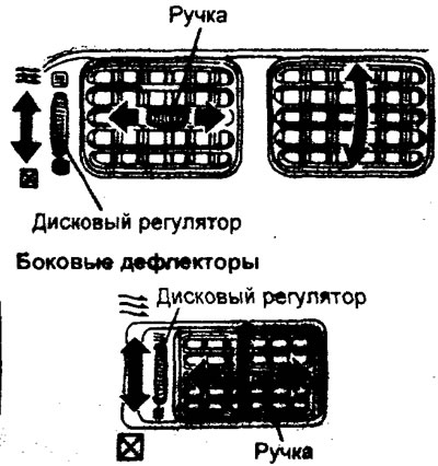
Central deflectors
Manual Heater and Air Conditioner Control Panel
Note: The location of the switches is shown in the figure "Manual Heater and Air Conditioner Control Panel".
1. Switch [3] is used to turn on the air conditioner (when the air conditioner is on, the indicator on the switch lights up). When pressed again, the air conditioner mode is turned off. The heater operates if the air conditioner mode is turned off.
2. The air intake mode selection switch [4] allows air to be taken either from outside the vehicle (ventilation) or from inside the vehicle (recirculation). The air intake location is selected by pressing the switch (in the "Recirculation" position, the indicator on the switch will light).
Note: The recirculation mode, especially in cold weather, should be used for a short period of time to avoid excessive fogging of the windows.
3. Switch [2] sets the rotation speed of the heater electric fan (air flow power). There are 4 positions for adjusting the fan rotation speed. Under normal conditions, it is recommended to set the switch to the first or second position. Position "O" - turns off the heater fan.
4. Switch [5] is used to set the air temperature in the passenger compartment. Turn the switch knob clockwise to increase the temperature. The heater is switched off if the switch is turned counterclockwise until it stops.
Note: If the engine coolant temperature is low, the temperature of the air entering the passenger compartment does not change, even when the switch is in the extreme right position.
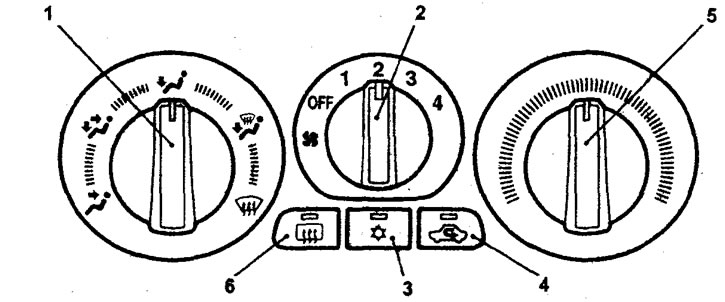
Manual heating and air conditioning control panel.
Note: For a description of the switches, see the "Manual Heater and Air Conditioner Control Panel" subsection.
5. If the rear window fogs up, press the rear window heater switch (6). The heater's operation is indicated by the indicator on the button lighting up. The heater operates for 15 minutes and switches off automatically. It is forcibly switched off by pressing the switch again.
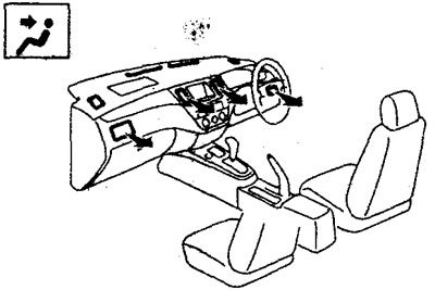
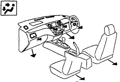
6. Switch [1] is used to select the air flow detection mode. To activate the desired mode, turn the handle to the appropriate position.
Note: The thickness of the arrow indicates the power of the air flow coming out of the deflector.
a) The air flow is directed towards the head area.
b) The air flow is directed to the head and floor area simultaneously.
c) The air flow is directed almost entirely towards the floor.
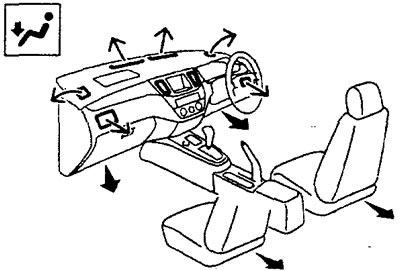
d) The air flow is directed to the windshield and to the floor.
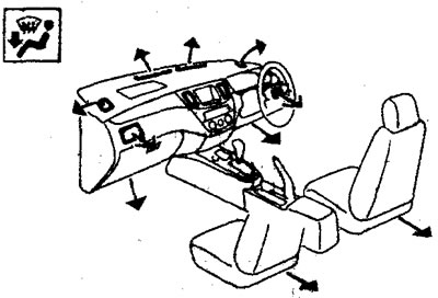
d) The air flow is directed to the windshield. This mode is used in case of fogging of the windshield.
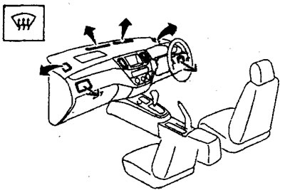
Automatic heater and air conditioner control panel
Note: The location of the switches is shown in the figure "Automatic Heater and Air Conditioner Control Panel".
1. Switch [3] ("
 ") is designed to turn on the air conditioner. When the air conditioner is running, the indicator on the switch is lit. When you press the switch again, the air conditioner will turn off.
Note: The blinking indicator may indicate a malfunction in the air conditioning system. If the indicator starts blinking, turn off the air conditioner and then turn it on again. If the indicator stops blinking, there is no malfunction.
2. Switch [4] (TEMP) is used to set the air temperature in the passenger compartment. The temperature can be changed within the range from 18°C to 32°C by turning the switch.
3. The air intake mode selection switch [5] (ventilation/recirculation) allows air to be taken in either from outside the vehicle or from the passenger compartment. The selection is made by pressing the switch (in the "Recirculation" position, the indicator on the switch will light).
4. To enable the automatic control mode of the air conditioner and heater (mode "AUTO"), you need to set the temperature with switch [4], then set switches [1] and [2] to the "AUTO" position and turn on the air conditioner with switch [3]. When the air conditioner is operating, the indicator on switch [3] will light
Note: when the "AUTO" mode is active, the system will automatically determine the required air intake mode depending on the set air temperature in the cabin. If the set air temperature in the cabin is low, the system will automatically switch to the recirculation mode for faster air cooling. If the set air temperature in the cabin is high, the system will automatically switch to the ventilation mode for faster air heating. If you try to change the air intake mode using the switches, the system will switch to the manual control mode of the heater and air conditioner.
5. Switch [2] sets the rotation speed of the electric fan (air flow power). There are 7 levels of fan rotation speed adjustment in total.
6. Switch [1] is used to change the mode of distribution of air flows supplied to the passenger compartment. To turn on the desired mode, turn the handle to the corresponding position.
Note: Air flow distribution for different modes is shown in the subsection "Manual Heater and Air Conditioner Control Panel".
7. If the rear window fogs up, press the rear window heater switch (6). The heater's operation is indicated by the indicator on the button lighting up. The heater operates for 20 minutes and switches off automatically. It is forcibly switched off by pressing the switch again.