
English Русский
Български
Беларускі
Український
Српски
Hrvatski
Română
Polski
Slovenský
Magyar
Articles Bookmark Contacts Sitemap   
Company Audi Company Ford Company Hyundai Company Kia Company Mazda Company Mercedes-Benz Company Nissan
MitsubishiMan.ru


Home Colt Lancer Galant L200 Outlander Pajero Others
Carisma (1995-2004) Space Star (1998-2005)

Electric motors for air conditioner damper control drives with automatic control (Mitsubishi Carisma)

  • Home
  • Mitsubishi
  • Carisma (1995-2004)
  • Body and interior
  • Air conditioner
  • Electric motors for air conditioner damper control drives with automatic control
0
Contents: Removal ⤓ Examination ⤓ Installation ⤓

Removal


To remove the air damper control drive motors, perform the following operations.

1. Disconnect the cable from the negative terminal of the battery.

2. Remove the radio.
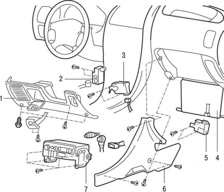


Fig. 18.8. Electric motors for air conditioner air damper control drives with automatic control: 1 – lower cover of the instrument panel; 2 – electric motor for driving external air exchange dampers; 3 – air mixing flap drive electric motor assembly; 4 – storage box; 5 – electric motor for driving the internal and external air exchange flaps; 6 – side cover (both sides); 7 – radio


3. Loosen the screws and remove the side covers 6 from both sides (Fig. 18.8).

4. Loosen the screws, disconnect the electrical connector and remove the air mixing flap drive motor 3 assembly.

5. Remove the lower instrument panel cover.

6. Remove the electric motor 2 of the external air exchange damper drive.

7. Remove the glove box.

8. Loosen the screws, disconnect the electrical connector and remove the electric motor 5 of the internal and external air exchange damper drive.


Examination
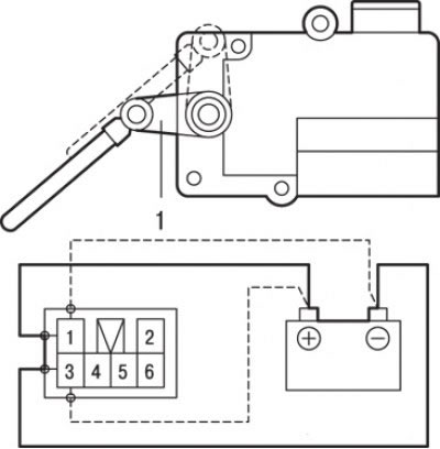


Fig. 18.9. Location of connector contacts and checking the electric motor of the internal and external air exchange dampers: 1 – lever for driving the internal and external air exchange flaps


1. When checking the electric motor of the internal and external air exchange dampers, make sure that the lever moves when battery voltage is applied to contacts "1" and "3" of the side connector of the electric motor (Fig. 18.9). Also make sure that when the polarity is changed, the lever moves in the opposite direction.

Warning! Turn off the power supply if the damper is inside or outside the duct. If the motor shaft does not rotate when power is applied, turn off the power supply.
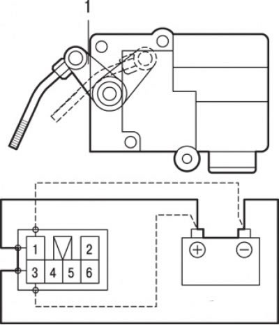


Fig. 18.10. Location of connector contacts and checking the air mixing flap drive electric motor: 1 – air mixing flap drive lever


2. When checking the air mixing flap drive motor, make sure that the lever moves when battery voltage is applied to contacts "1" and "3" of the side connector of the electric motor (Fig. 18.10). Also make sure that when the polarity is changed, the lever moves in the opposite direction.

Caution! Turn off the power supply if the damper is in the "MAX HOT" or "MAX COOL" position. If the motor shaft does not rotate when power is supplied, turn off the power supply.
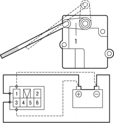


Fig. 18.11. Location of connector contacts and checking the electric motor of the external air exchange damper drive: 1 – lever for driving external air exchange


3. When checking the electric motor of the outside air exchange flap drive, make sure that the lever moves when battery voltage is applied to contacts "1" and "3" of the side connector of the electric motor (Fig. 18.11). Also make sure that when the polarity is changed, the lever moves in the opposite direction.

Caution! Turn off the power supply if the throttle is in the "DEF" or "FACE" position. Turn off the power supply if the motor shaft does not rotate when power is applied.


4. When checking the potentiometer, connect the tester to terminals "2" and "5" of the electric motor assembly connector and check that the resistance changes smoothly when moving the valve from the "DEF" position to the "FACE" position (see Fig. 18.11).

Nominal resistance, kOhm:
  • "DEF" position – about 4.82;
  • "FACE" position - about 0.18.

Installation


Installation is carried out in the reverse order of removal.
This article is available at: russian, bulgarian, belarusian, ukrainian, serbian, croatian, romanian, polish, slovak, hungarian
This article was reviewed by: Dmitry Vasiliev
Share with friends:
◀ Previous
Carisma: Air conditioner
Next ▶

Panel and electronic control unit of air conditioning with automatic control
Heater control panel and manual air conditioner switch
Working with tubes, hoses and their connections
Checking the receiver/dryer
Checking the electromagnetic clutch of the air conditioner compressor
Heater and heater radiator — removal and installation
Heater Fan and Resistor — Removal and Installation
Ventilation system air ducts — removal and installation
Air Purification Filter — Checking and Replacing
Cleaning the collector and ionizer
Similar materials for other Mitsubishi models

➤ Scheme 5. Automatic transmission control system Mitsubishi Colt 4 and 5 (1991-2003)
➤ Adjusting the Automatic Transmission Throttle Control Cable Mitsubishi Lancer 3 and 5 (1984-1992)
➤ Removal and installation the heater and air conditioner… Mitsubishi Galant 6 and 7 (1987-1998)
➤ Control and emergency indicator lights Mitsubishi L200 4 (2005-2014, diesel)
➤ Electric window control Mitsubishi Outlander 1 (2003-2008)
➤ Air Conditioner Control Unit — Removal and Installation Mitsubishi Pajero 1 and 2 (1982-1999)
Link in different formats to this article
Comments and feedback from visitors
No comments yet


Add up two numbers 36 + 35


Carisma (1995-2004) 
  • General information
  • User manual
  • Maintenance
  • Power unit
  • Petrol engines 4G9
  • Diesel engines FBQT
  • Diesel engines F9Q
  • Cooling system
  • Injection system (MPI)
  • Injection system (GDI)
  • Engine electrical equipment
  • Transmission
  • Clutch
  • Mechanical gearbox
  • Automatic gearbox
  • Chassis and running gear
  • Steering
  • Brake system
  • Front suspension and shafts
  • Rear suspension
  • Body and interior
  • Exterior (external elements)
  • Interior (internal elements)
  • Doors, locks and windows
  • Air conditioner
  • Electrical equipment
  • Equipment and devices
  • Headlights and lighting
  • Electrical circuits
Space Star (1998-2005) 
  • General information
  • User manual
  • Maintenance
  • Power unit
  • Petrol engines 4G9
  • Petrol engines 4G1
  • Diesel engines F9Q1
  • Cooling system
  • Fuel injection system GDI
  • Fuel injection system MPI
  • Diesel supply system F9Q1
  • Ignition system
  • Diesel preheating
  • Transmission
  • Clutch
  • Mechanical gearbox
  • Automatic gearbox
  • Chassis and running gear
  • Suspension and drive shafts
  • Brake system
  • Steering
  • Body and interior
  • Exterior (external elements)
  • Interior (internal elements)
  • Doors, locks and windows
  • Heating and air conditioning
  • Electrical equipment
  • Power devices
  • Equipment and devices
MitsubishiMan.ru © 2018–2026 • Mobile version • Articles about Mitsubishi • Contacts • Sitemap: EN BG BY UA RS HR RO PL SK HU • Site search • Bookmark
Colt 2 and 3 (1983-1993) · Colt 4 and 5 (1991-2003) · Colt 5 (1995-2003) · Lancer 3 and 5 (1984-1992) · Lancer 9 (2000-2007) · Galant 5 (1983-1989) · Galant 6 and 7 (1987-1998) · L200 4 (2005-2014) · Outlander 1 (2003-2008) · Pajero 1 and 2 (1982-1999) · Pajero 4 (2006-2021) · Carisma (1995-2004) · Space Star (1998-2005) ·
This resource sets cookies 🍪 to avoid bothering you with repeated data entry.