



Removal
To remove the air cleaning filter, follow these steps.
1. Disconnect the cable from the negative terminal of the battery.
Caution! After the power is turned off (the fan switch is in the "OFF" position or the ignition switch is in the "ACC" or "LOCK" position), high pressure remains in the air cleaning filter for about 5 seconds. Accordingly, wait about 5 seconds after turning off the power before removing the air cleaning filter.
2. Remove the bottom cover.
3. Remove the glove box.
4. Remove the corner cover.
5. Remove the glove box frame.
6. Remove the side panel (passenger side).
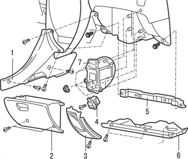
Fig. 18.17. Air cleaning filter: 1 – side panel (passenger side); 2 – storage box; 3 – corner cover; 4 – power transistor; 5 – glove box frame; 6 – bottom cover; 7 – air cleaning filter assembly
7. Loosen the screws and remove power transistor 4 (Fig. 18.17).
8. Loosen the screws and remove the air cleaning filter 7 assembly.
Disassembly
To disassemble the air cleaning filter, perform the following operations.
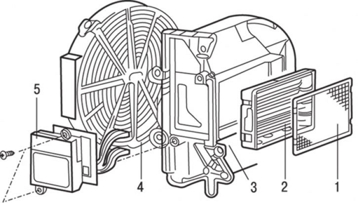
Fig. 18.18. Air cleaning filter parts: 1 – mesh filter element; 2 – ionizer; 3 – air cleaning filter housing; 4 – collector; 5 – transformer unit
1. Remove the mesh filter element 1 (Fig. 18.18).
2. Remove ionizer 2 from the housing.
3. Remove manifold 4.
4. Remove the transformer assembly 5.
Examination
When checking the ionizer, measure the voltage at the collector and at the ionizer as follows.
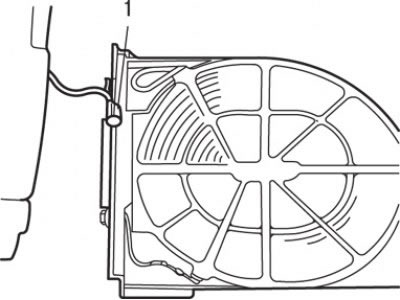
Fig. 18.19. Location of the air purifier connector (1) when checking the ionizer and voltage in the collector
1. Move the air cleaning filter to the opposite side and connect the connector so that the unit can operate (Fig. 18.19).
Caution! Do not connect the power transistor.
2. Connect the high voltage probes (capable of measuring voltage up to 10,000 V) to the digital tester.
Attention! When taking measurements, be careful not to short-circuit the terminals.
3. Start the engine and set the fan switch to the "HI" position.
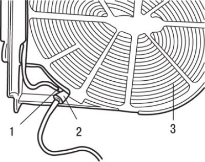
Fig. 18.20. Connecting the negative probe of the high-voltage tester to the negative terminal on the collector side: 1 – "minus" terminal on the collector side; 2 – "minus" probe of the high-voltage tester; 3 – collector
4. Connect the negative ("–") probe of the high-voltage tester to the negative ("–") terminal on the collector side (Fig. 18.20).
If the measured voltage when the high-voltage probe ("+") touches the ("+") terminal on the collector side is not lower than 2000 V, then the collector can be considered serviceable.
[Original material on the website: MitsubishiMan.ru]
If the measured voltage when touching the ("+") probe of the high-voltage tester to the ("+") terminal on the ionizer side is not lower than 4000 V, then the air ionizer can be considered to be in good working order.