



Removal
To remove, follow these steps.
1. Disconnect the cable from the negative terminal of the battery.
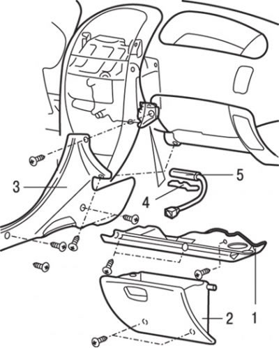
Fig. 18.22. Heater coolant temperature sensor: 1 – bottom cover; 2 – storage box; 3 – side cover; 4 – bracket for fastening the coolant temperature sensor in the heater; 5 – heater coolant temperature sensor
2. Remove the bottom cover 1 (Fig. 18.22).
3. Remove glove box 2.
4. Remove the side cover 3.
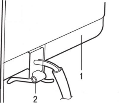
Fig. 18.23. Removing the bracket for fastening the coolant temperature sensor in the heater: 1 – heater unit; 2 – bracket for fastening the working fluid temperature sensor in the heater
5. Remove the heater coolant temperature sensor mounting bracket from the base of the heater unit by moving it toward the front of the vehicle (Fig. 18.23).
6. Remove sensor 5 (see Fig. 18.22) of the coolant temperature in the heater and disconnect the electrical connector.
Examination
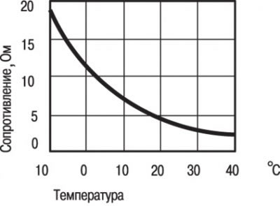
Fig. 18.24. Graph of the dependence of the resistance of the coolant temperature sensor in the heater on the temperature
When measuring the resistance at the sensor connector contacts at two or more temperature levels, the resistance values should match the curve of the graph shown in Fig. 18.24.
Attention! The temperature values at which the test is carried out must not exceed the range shown in the graph.
Installation
Installation is carried out in the reverse order of removal, taking into account the following.
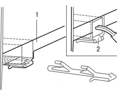
Fig. 18.25. Installing the sensor mounting bracket on the base of the heater unit: 1 – heater unit; 2 – limiter
1. Install the sensor mounting bracket on the base of the heater unit (Fig. 18.25).
2. Move the temperature sensor until it rests against the limiter of the sensor mounting bracket.