



Contents: Removal ⤓ Installation ⤓
Removal
1. Drain the brake fluid.
2. Disconnect the parking brake cable (Fig. 15.53).
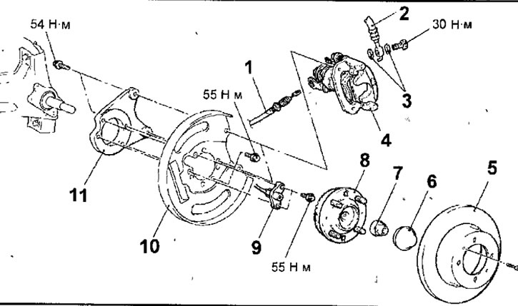
Fig. 15.53. Rear disc brake: 1 - parking brake cable connection; 2 - brake hose; 3 - sealing gasket; 4 - support; 5 - brake disc; 6- hub cap; 7 - self-locking nut, 175 Nm; 8 - rear wheel hub assembly; 9 - rear wheel speed sensor; 10 - support shield; 11 - Disc brake adapter
3. Remove the hollow bolt and disconnect the brake hose from the caliper.
4. Remove the sealing gaskets.
5. Unscrew the bolts and remove the caliper.
6. Unscrew the bolts and remove the brake disc.
7. Using a screwdriver as a lever, remove the hub cap.
8. Unscrew the self-locking hub mounting nut.
9. Remove the rear wheel hub assembly.
10. Remove the bolts and rear wheel speed sensor.
11. Remove the bolts and disc brake support plate and adapter.
Installation
Installation is carried out in the reverse order of removal, taking into account the following.
1. Using a spring dynamometer, measure the moment of resistance to rotation of the wheel hub bearing with the brake pads removed (Fig. 15.54).
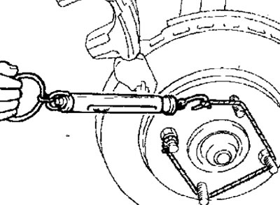
Fig. 15.54. Using a spring dynamometer to measure the torque of a wheel hub bearing with the brake pads removed
2. After installing the caliper assembly, install the brake pads assembly.
Warning: Do not allow oil, grease or other contaminants to come into contact with the working surfaces of the brake pads and brake disc.
3. If new brake pads are to be installed, use a special tool to press the piston into the caliper cylinder (Fig. 15.55). When the piston is pressed, the brake fluid is forced out of the brake cylinder into the reservoir. Therefore, constantly monitor the fluid level in the reservoir and, if necessary, pump it out.
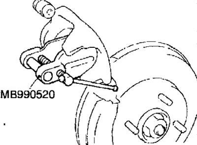
Fig. 15.55. Using a special tool to press the piston into the caliper cylinder
4. Be careful not to damage the piston dust boot when lowering the caliper into place, then install the guide pin.
5. Start the engine and press the brake pedal 2-3 times.
6. Turn off the engine.
7 Turn the brake disc 10 turns in the forward direction.
8. Using a spring dynamometer, measure the moment of resistance to rotation of the hub bearing (Fig. 15.56).
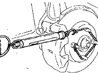
Fig. 15.56. Using a spring dynamometer to measure the torque of a wheel hub bearing
9. Calculate the moment of resistance to rotation of new brake pads as the difference between the moments during rotation of the hub with brake pads and without brake pads.
The moment of resistance to rotation of the disc brake: no more than 20 N
10. If the calculated torque difference exceeds the nominal value, remove and clean the caliper piston, and check the condition of the caliper guide pins.
[The text of the article was taken from the website www.MitsubishiMan.ru]
11. When installing the rear wheel speed sensor, be careful when handling the sensor tip to avoid damaging it. Insert a feeler gauge into the gap between the rear wheel speed sensor tip and the toothed surface of the ABS sensor rotor and check whether the gap matches the nominal value around the entire perimeter of the rotor (Fig. 15.57).
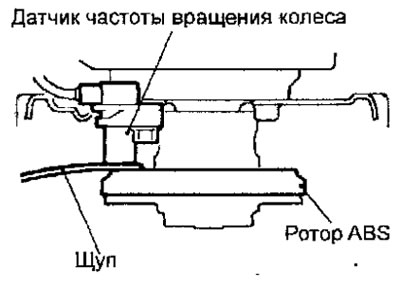
Fig. 15.57. Checking the gap between the rear wheel speed sensor tip and the toothed surface of the ABS sensor rotor
Nominal clearance: 0.1-1.9 mm