



Contents: Removal ⤓ Installation ⤓
Warning: The hose marked *1in figures 15.34 and 15.35 and the hose marked *in figure 15.36, after disconnecting from the reservoir, do not lower it below the master brake cylinder, otherwise air will enter the hydraulic brake circuits. *2 indicates vehicles with ABS.
Removal
- Drain the brake fluid.
- Remove the air filter.
- Remove the fuse and relay box.
- Remove the activated carbon canister.
- On a 1.9L diesel vehicle with a left-hand drive, remove the air filter, relay box and activated carbon canister.
- Disconnect the connector from the brake fluid level sensor (Fig. 15.34, 15.35).
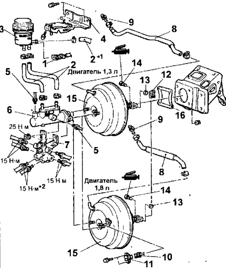
Fig. 15.34. The main brake cylinder and brake booster of a left-hand drive vehicle: 1 - brake fluid level sensor connector; 2 - hoses; 3 - refill tank; 4 - tank bracket; 5 - connecting nut for fastening the brake pipe, 15 Nm; 6 - master brake cylinder assembly; 7 - pressure limiter bracket; 8 - vacuum hose (with built-in check valve); 9 - adapter, 15-18 Nm; 10 - vacuum sensor connector; 11 - vacuum sensor; 12 - retainer; 13 - washer; 14 - bolt; 15 - brake booster; 16 - gasket
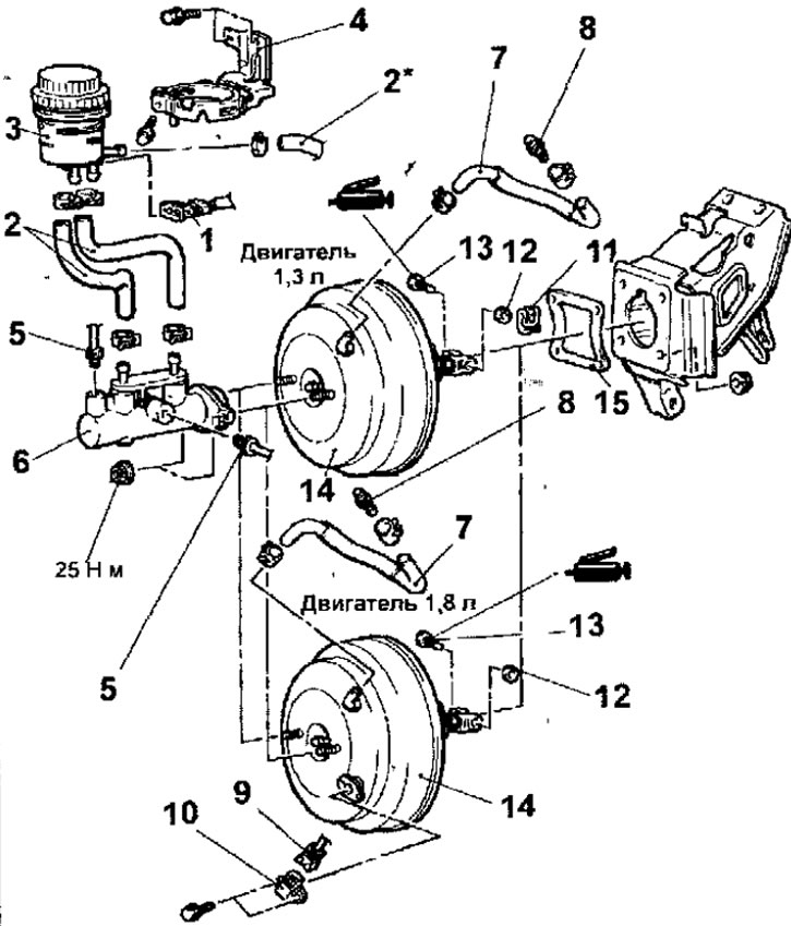
Fig. 15.35. The main brake cylinder and brake booster of a right-hand drive vehicle: 1 - brake fluid level sensor connector; 2 - hoses; 3 - refill tank; 4 - tank bracket; 5 - connecting nut for fastening the brake pipe, 15 Nm; 6 - master brake cylinder assembly; 7 - vacuum hose (with built-in check valve); 8 - adapter, 15-18 Nm; 9 - vacuum sensor connector; 10 - vacuum sensor; 11 - retainer; 12 - washer; 13 - bolt: 14 - brake booster; 15 - gasket
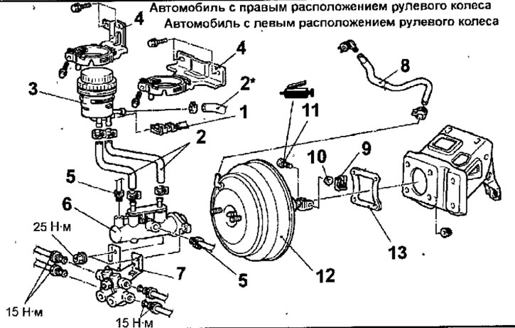
Fig. 15.36. Brake master cylinder and brake booster of a 2000 model with a 1.9 L diesel engine: 1 - brake fluid level sensor connector; 2 - hoses; 3 - refill tank; 4 - tank bracket; 5 - connecting nut for fastening the brake pipe, 15 Nm; 6 - master brake cylinder assembly; 7 - pressure limiter bracket; 8 - vacuum hose (with built-in check valve); 9 - retainer; 10 - washer; 11 bolt; 12 - brake booster; 13 - gasket
- Loosen the clamps and disconnect the hoses from the refill tank.
- Remove the refill tank.
- Remove the bolts and the tank bracket.
- Loosen the connecting nuts and disconnect the brake pipes from the master cylinder.
- Loosen the nuts and remove the brake master cylinder assembly and the pressure limiter bracket.
- Loosen the clamps and remove the vacuum hose (with built-in check valve).
- Unscrew the adapter from the brake booster.
- Disconnect the vacuum transmitter connector.
- Unscrew the bolts and remove the vacuum sensor
- Remove the retainer and washer, then remove the bolt.
- Remove the brake booster and gasket.
Installation
- Installation is carried out in the reverse order of removal, taking into account the following.
- Before screwing the adapter into the brake booster, apply a thin layer of sealant ЗМ ATD Part # 8661 to its threads (Fig. 15 37).
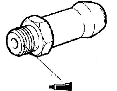
Fig. 15.37. Place of application of sealant ЗМ ATD Part # 8661 on the adapter thread
- When installing the master brake cylinder assembly, it is necessary to adjust the clearance between the brake booster pushrod and the primary piston. Clearance A (Fig. 15.38) is defined as the difference in the values of measurements B, C and D, A = B - CD.
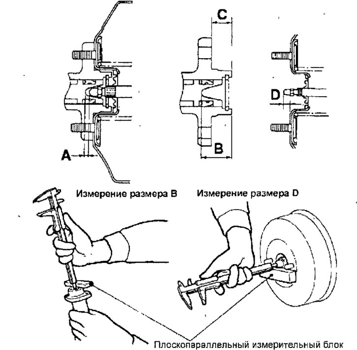
Fig. 15.38. Checking the clearance between the brake booster pushrod and the primary piston
Nominal value: 0.6 - 0.8 mm
- If the clearance value does not correspond to the nominal value, adjust it by changing the length of the pusher by turning the pusher adjusting screw (Fig. 15.39).
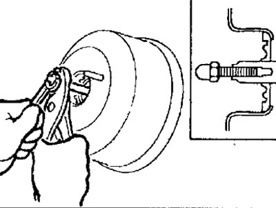
Fig. 15.39. Changing the length of the pusher by turning the pusher adjusting screw
- Place the vacuum hose all the way into the hexagon of the connecting pipe on the engine intake manifold and secure the hose with a clamp.
- Connect the brake pipes to the pressure regulator as shown in Figure 15.40.
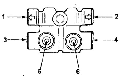
Fig. 15.40. Connecting the brake pipes to the pressure regulator: 1 - pressure regulator - brake mechanism of the left rear wheel; 2 - pressure regulator - brake mechanism of the right front wheel; 3 - pressure regulator - brake mechanism of the right rear wheel; 4 - pressure regulator - brake mechanism, left front wheel; 5 - pressure regulator - secondary chamber of the master brake cylinder; 6 - pressure regulator - primary chamber of the main brake cylinder
- Install a canister of activated carbon.
- Install the fuse and relay box.
- Install the air filter.
- Fill with brake fluid.
- Remove air from the hydraulic drive of the brake system.
- Adjust the position of the brake pedal.