



Contents: Table of checking the brake disc…⤓ Checking the thickness of the brake…⤓ Checking the brake disc runout ⤓ Correction of brake disc runout ⤓
Warning: When servicing disc brakes, special attention must be paid to compliance with the technical requirements for disc brakes, which ensure the normal operation of the disc brakes.
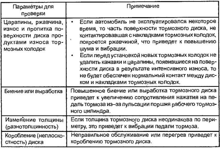
Before carrying out mechanical or grinding restoration operations on the brake disc, the following parameters listed in the table must be checked.
Table of checking the brake disc parameters before its restoration
Checking the thickness of the brake disc
1. Using a micrometer, measure the thickness of the brake disc at eight points approximately every 45° at a distance of 10 mm from the outer edge of the disc (Fig. 15.22).
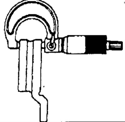
Fig. 15.22. Using a micrometer to measure the thickness of a brake disc
The difference in disc thickness between any measured points must not exceed 0.015 mm.
Brake disc thickness:
- nominal: 24.0 mm;
- minimum allowable: 22.4 mm.
2. The brake disc must be replaced if its thickness has become less than the minimum permissible value. If the disc thickness difference exceeds the permissible value, replace the disc or turn it on a special lathe.
Checking the brake disc runout
1. Unscrew the two caliper mounting bolts, lift the caliper and secure it to the front suspension strut with wire (Fig. 15.23).
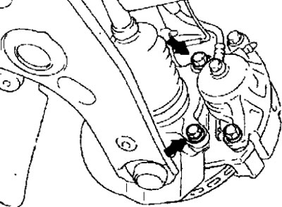
Fig. 15.23. Location of front brake caliper mounting bolts
2. Slowly turn the brake disc and visually check its condition; on both sides. Brake disc wear; from the pads must be within acceptable limits. If there are cracks on the disk, the disk must be replaced.
Before processing the brake disc, check its condition.
3. Use a pointer indicator to check the runout of the brake disc. Attach the indicator in any convenient place and, turning the brake disc, determine its runout at a distance of 5 mm from the outer edge (Fig. 15.24). Before checking the runout of the brake disc, make sure that the hub bearing is in good condition.
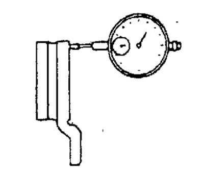
Fig. 15.24. Checking the brake disc runout
Maximum permissible runout of the brake disc: 0.06 mm
Note: Tighten the wheel nuts to secure the brake disc to the hub.
Correction of brake disc runout
1. If the brake disc runout is within or exceeds the limit value, it is necessary to change the relative position of the disc and hub and then measure the runout again.
(1) Before removing the brake disc, use chalk i to make marks on both sides of the wheel mounting stud at the point of maximum runout (Fig. 15.25).
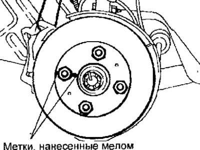
Fig. 15.25. Placement of marks at the point of maximum runout of the brake disc
(2) Remove the brake disc and install a dial indicator as shown in Figure 15.26. While moving the hub axially, measure the axial play in the hub bearing. If the axial play is equal to or greater than the limit value, remove the hub and check the steering knuckle and hub.
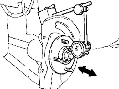
Fig. 15.26. Installing a pointer-type indicator to measure axial play in a hub bearing
Maximum permissible axial play: 0.05 mm
(3) If the axial play in the hub bearing does not exceed the limit value, turn the brake disc 180° relative to the chalk line, install it on the hub and repeat the brake disc runout measurement again (Fig. 15.27).
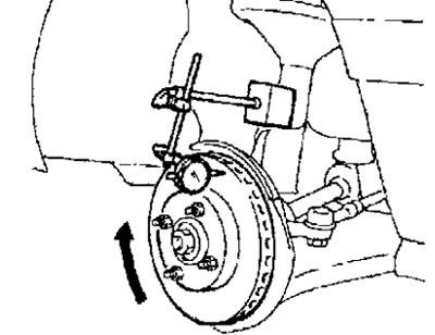
Fig. 15.27. Checking the brake disc runout
2. If the operations performed do not eliminate the increased runout of the disc, replace the brake disc or process it on a special lathe.
Note: If a brake disc needs to be replaced, the other brake disc must also be replaced to ensure uniform braking. When replacing the brake discs, the brake pads must also be replaced.