



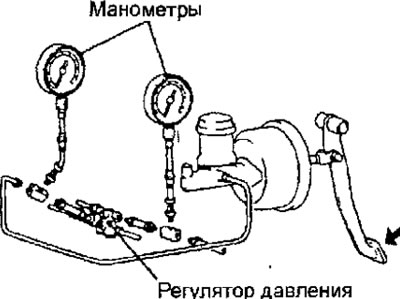
Fig. 15.13. Connecting pressure gauges to the input and output of the pressure regulator
2. Remove air from the hydraulic brake drive and pressure gauges.
3. While gradually depressing the brake pedal, take the following measurements and check that the measured values are within the tolerance.
(1) Check that the outlet pressure begins to drop relative to the inlet pressure (switch-on point) (Fig. 15.14).
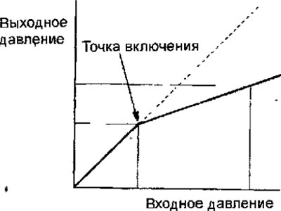
Fig. 15.14. Dependence of the pressure at the outlet of the pressure regulator on the pressure at the inlet of the pressure regulator.
Nominal value: 2.45 MPa
(2) Check that when the brake pedal pressure increases, the fluid pressure at the outlet is within 4.30 + 0.4 MPa, while the inlet pressure is 9.81 MPa.
(3) The pressure differential at the outlet between the right and left circuits of the hydraulic drive of the brake system must not exceed 0.4 MPa.
[The original article was published on MitsubishiMan]
4. If the pressure measurement results do not correspond to the required values, replace the pressure regulator.