



Contents: Removal ⤓ Installation ⤓
Removal
1. Drain the brake fluid.
2. Remove the air conditioner relay box.
3. Pull the lock in the direction of the arrow shown in figure 15.74, and disconnect the connector from the control unit.
4. Loosen the nuts and disconnect the brake system pipes (Fig. 15.77).
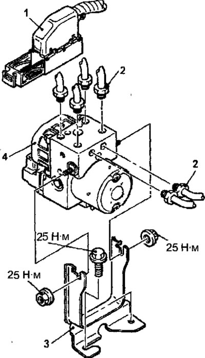
Fig. 15.77. Hydraulic block: 1 - ABS control unit connector; 2 - connecting nut for fastening the brake system tube, 15 Nm, 3 - hydraulic unit bracket; 4 - hydraulic block
5. Unscrew 2 bolts and remove the hydraulic unit bracket.
6. Remove the hydraulic block assembly.
Warnings!
- 1. The hydraulic unit assembly cannot be disassembled, therefore it is prohibited to loosen any bolts and nuts.
- 2. Do not turn over or lay the hydraulic unit on its side.
Article reprinted from the website: MITSUBISHIMAN.ru
Installation
1. Installation is carried out in the reverse order of removal, taking into account the following.
2. Connect the brake pipes to the hydraulic unit as shown in Figure 15.78.
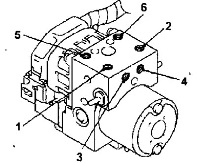
Fig. 15.78. Connecting the brake pipes to the hydraulic unit: 1 - from the main brake cylinder (primary chamber); 2 - to the pressure regulator (right wheel); 3 - to the front right brake mechanism (left wheel); 4 - from the main brake cylinder (secondary chamber); 5 - to the pressure regulator (left wheel); 6 - to the front right brake mechanism (right wheel)
3. Install the air conditioner relay box.
4. Fill with brake fluid.
5. Remove air from the hydraulic drive of the brake system.
6. Adjust the position of the brake pedal.