



Removal
1. Check the output voltage of the wheel speed sensor.
Front sensor
1. Loosen the bolts and remove the front wheel speed sensor (Fig. 15.79).
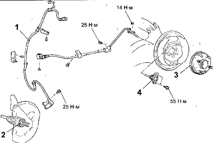
Fig. 15.79. Front and rear wheel speed sensors: 1 - front wheel speed sensor; 2 - Front wheel speed sensor rotor: 3 - Rear wheel speed sensor rotor; 4 - rear wheel speed sensor
Rear sensor
1. Remove the bolts and rear wheel speed sensor.
2. Remove the rear wheel speed sensor rotor.
Examination
- Check for any metal particles on the surface of the 3-pole sensor tip and remove them if present.
- Since the speed sensor has a magnet inside, the sensor pole is magnetized, causing foreign metal materials to be easily attracted to it. In addition, if the sensor pole piece is damaged, the sensor will not be able to detect the wheel speed correctly.
- Measure the resistance value between the terminals of the sensor connector, which should be within 1.28-1.92 kOhm (Fig. 15.80).
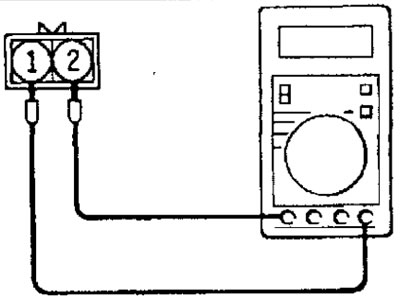
Fig. 15.80. Checking the resistance of the wheel speed sensor
(The source of the article is available at mitsubishiman.ru)
- If the internal resistance of the wheel speed sensor does not correspond to the nominal value, replace the sensor.
- Check for damage, breakage or poor contact in the sensor wires, if any, replace the wire with a new one. To check for damage in the sensor wire, remove the wire mounting bracket from the body, then bend and pull the wire to check for temporary lack of contact.
Installation
1. Installation is carried out in the reverse order of removal.
2. When installing the rear wheel speed sensor, be careful when handling the sensor tip to avoid damaging it. Insert a feeler gauge into the gap between the rear wheel speed sensor tip and the toothed surface of the ABS sensor rotor and check whether the gap is within the standard value around the entire perimeter of the rotor (fig. 15.57).
Nominal clearance: 0.1-1.9 mm