



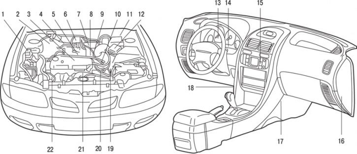
Fig. 7.1. Location of SOHC injection system components: 1 – air conditioning compressor electromagnetic clutch relay; 2 – electromagnetic valve for purging the adsorber (for right-hand drive vehicles); 3 – knock sensor; 4 – fuel pump service connector; 5 – injectors; 6 – electromagnetic atmospheric valve (cars with TCL system); 7 – Throttle position sensor (for vehicles with TCL system); 8 – engine idle speed controller (ISC servo); 9 – Accelerator pedal position sensor (with fully closed throttle position switch) (vehicles with TCL system); 10 – ignition distributor (with ignition coil, power transistor, TDC sensor and crankshaft position sensor); 11 – electromagnetic valve for purging the adsorber (for left-hand drive vehicles); 12 – air flow meter sensor (with intake manifold air temperature sensor and atmospheric (barometric) pressure sensor; 13 – vehicle speed sensor; 14 – Engine malfunction indicator lamp; 15 – air conditioner switch; 16 – electronic engine control unit; 17 – control relay (control relay); 18 – diagnostic connector; 19 – starter lock switch (automatic transmission selector switch); 20 – coolant temperature sensor; 21 – oxygen concentration sensor; 22 – sensor (sensor-switch) of fluid pressure in the hydraulic system of the power steering
The distributed fuel injection system consists of sensors and actuators that operate on commands from the engine control unit (engine-ECU). The sensors record the engine condition and transmit information to the electronic control unit, on the basis of which the unit controls the engine operation. The location of the SOHC and DOHC injection system elements is shown in Fig. 7.1 and 7.2.
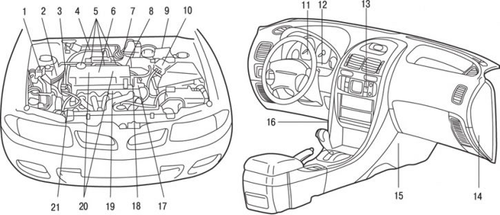
Fig. 7.2. Location of DOHC injection system components: 1 – air conditioning compressor electromagnetic clutch relay; 2 – crankshaft position sensor; 3 – camshaft position sensor; 4 – fuel pump service connector; 5 – injectors; 6 – knock sensor; 7 – throttle position sensor (with fully closed throttle position switch); 8 – engine idle speed controller (ISC servo); 9 – electromagnetic valve for purging the adsorber (fuel vapor recovery system); 10 – air flow meter sensor (with intake manifold air temperature sensor and atmospheric (barometric) pressure sensor); 11 – vehicle speed sensor; 12 – Engine malfunction indicator lamp; 13 – Air conditioning switch; 14 – electronic engine control unit; 15 – control relay (control relay); 16 – diagnostic connector; 17 – coolant temperature sensor; 18 – ignition system malfunction sensor; 19 – oxygen concentration sensor; 20 – ignition coils; 21 – sensor (sensor-switch) of fluid pressure in the hydraulic system of the power steering
The unit controls fuel injection, idle speed and ignition timing. In addition, the control unit has a number of diagnostic modes to simplify troubleshooting.
The moment the injector begins to open and the duration of its open state are set in such a way that the engine receives a fuel-air mixture of optimal composition, corresponding to the continuously changing operating conditions of the engine.
The injector is installed on the intake manifold of each cylinder. Fuel under pressure is supplied by the fuel pump from the tank to the fuel rail. The pressure is maintained by the pressure regulator. In the fuel rail, fuel under a certain pressure is distributed to each injector.
Under normal conditions, fuel is injected once every two crankshaft revolutions for each cylinder.
The order of cylinder firing is 1–3–4–2. This mode is called sequential fuel injection. The electronic control unit ensures enrichment of the fuel-air mixture during engine warm-up, as well as during operation under maximum load, controlling the mixture composition without feedback ("open-loop").
If the engine is warmed up or operates in partial modes, the control unit ensures the maintenance of the stoichiometric (theoretically necessary for complete combustion of fuel) composition of the fuel-air mixture, implementing feedback control ("closed-loop") by the composition of the mixture using signals from the oxygen concentration sensor. This ensures maximum efficiency of the three-way catalytic converter.
The electronic engine control unit maintains the optimum idle speed depending on external conditions and engine load by regulating the amount of air entering the engine through the bypass channel bypassing the throttle valve. The engine control unit controls the servo drive of the idle speed controller (ISC), ensuring that the set speed is maintained depending on the coolant temperature and the air conditioner load. In addition, when the air conditioner is turned on and off while the engine is idling, the stepper motor of the idle speed controller (ISC) doses the amount of additional air in such a way as to eliminate fluctuations in the crankshaft speed.
The power transistor connected to the primary circuit of the ignition coil closes and opens the circuit. This ensures optimal control of the ignition advance angle in accordance with the engine operating mode.
The electronic engine control unit determines the optimum ignition timing angle depending on the engine crankshaft speed, the volumetric air flow entering the engine, the coolant temperature and atmospheric pressure.
The fuel tank is located under the rear seat floor to provide passive safety and increase luggage space.
To prevent fuel from leaking out of the tank in the event of an accident (car overturning), a fuel shut-off valve is installed in the fuel vapor discharge line.
In order to reduce weight and increase corrosion resistance, the fuel tank is made of plastic.