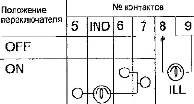
Contents: Removal ⤓ Installation ⤓ Checking the Fan Switch ⤓ Checking the air recirculation switch ⤓ Checking the air conditioner switch ⤓
Removal
- Remove the lower center panel from the instrument panel.
- Remove the glove compartment.
- Remove the radio.
- Remove the screws, pull the heater, fan and air conditioning control unit out of the instrument panel and disconnect the cables and electrical connector (Fig. 18.12).
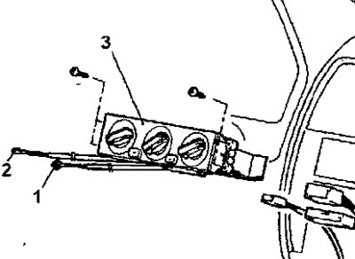
Fig. 18.12. Heater, fan and air conditioning control unit: 1 - air temperature control flap drive cable; 2 - air flow distribution flap drive cable; 3 - control unit for heater, fan and air conditioning system
Installation
- Set the air distribution control knob to the DEF position.
- Set the air distribution flap drive lever to the DEF position (turn the lever clockwise until it stops) and connect the cable to the lever (Fig. 18.13).
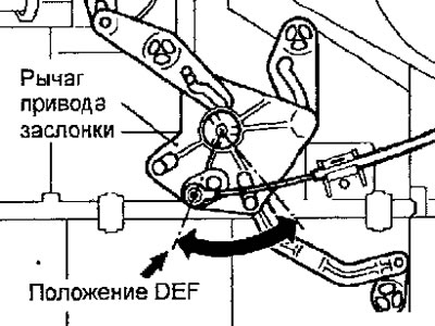
Fig. 18.13. Connecting the cable to the air flow distribution flap drive lever
- Set the temperature control knob to the MAX HOT (maximum heating) position.
- Set the air temperature control flap drive lever to the MAX HOT position (turn the lever clockwise until it stops) and connect the cable to the lever.
Checking the Fan Switch
- Check the conductivity between the fan switch contacts (Fig. 18.14)
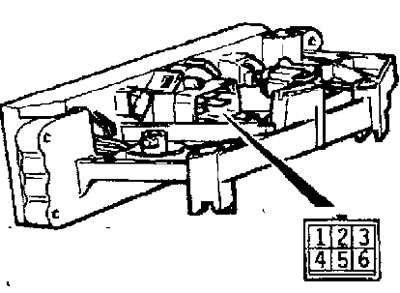
Fig. 18.14. Location of fan switch and connector contacts
(The text of the article was taken from the website: MitsubishiMan.ru)
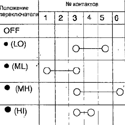
- If the conductivity is different from the required value, replace the fan switch.
Checking the air recirculation switch
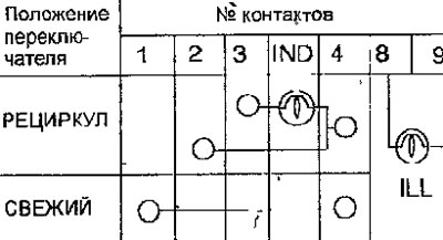
- Check the conductivity between the air recirculation switch contacts (Fig. 18.15)
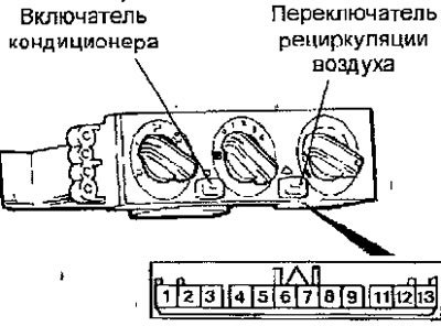
Fig. 18.15. Location of air recirculation switch, air conditioner switch and connector contacts
Checking the air conditioner switch
- Check the conductivity between the contacts of the air conditioner switch (Fig. 18.15)