



Contents: Removal ⤓ Checking the heater fan motor ⤓ Checking the resistor ⤓ Checking the fresh/recirculated air…⤓ Installation ⤓
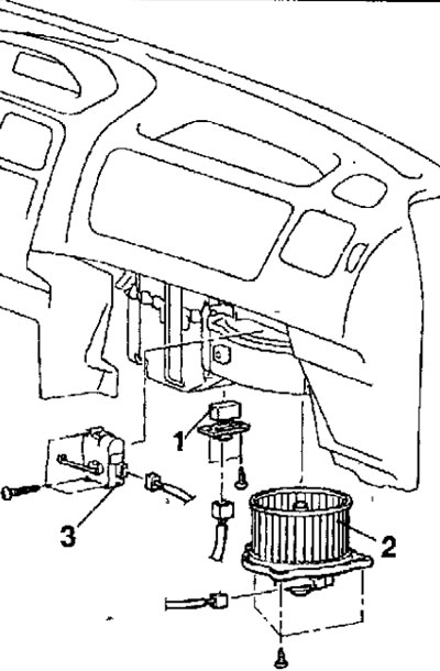
Fig. 18.17. Heater fan and resistor: 1 - resistor; 2 - heater fan; 3-motor for fresh/recirculated air supply flap drive
Removal
- Disconnect the cable from the negative battery terminal.
- Remove the glove box.
- Remove the lower panel from the passenger side of the instrument panel.
- Disconnect the connector, remove the bolts and remove the fan resistor.
- Disconnect the connector, unscrew the bolts and remove the heater fan.
Checking the heater fan motor
- Use additional wires to supply voltage from the battery to the fan motor connector contacts (Fig. 18.18). If the fan motor rotates and does not create any extraneous noise, it is in good working order.
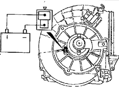
Fig. 18.18. Checking the heater fan motor
Checking the resistor
- Measure the resistance between the contacts of the heater resistor connector (Fig. 18.19).
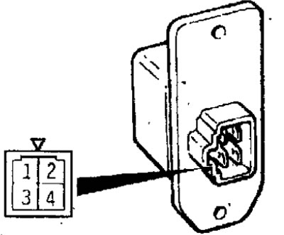
Fig. 18.19. Resistor connector pin location
Resistance:
- between contacts 3-2 (LO)-2.30 Ohm
- between contacts 3-4 (ML) -1.10 Ohm
- between contacts 3-1 (MN) - 0.40 Ohm
Checking the fresh/recirculated air damper drive motor
- Make sure that when the positive terminal of the battery is connected to terminal 1 of the connector and the negative terminal is connected to terminal 2 of the connector, the air supply mode flap actuator moves the flap to the fresh air supply position (Fig. 18.20).
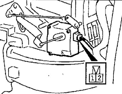
Fig. 18.20. Location of contacts of the fresh/recirculated air flap drive motor connector
- Make sure that when the positive battery terminal is connected to terminal 3 of the connector and the negative battery terminal is connected to terminal 1 of the connector, the air intake flap actuator moves the flap to the recirculated air position.
Installation
- Installation is carried out in the reverse order of removal.