



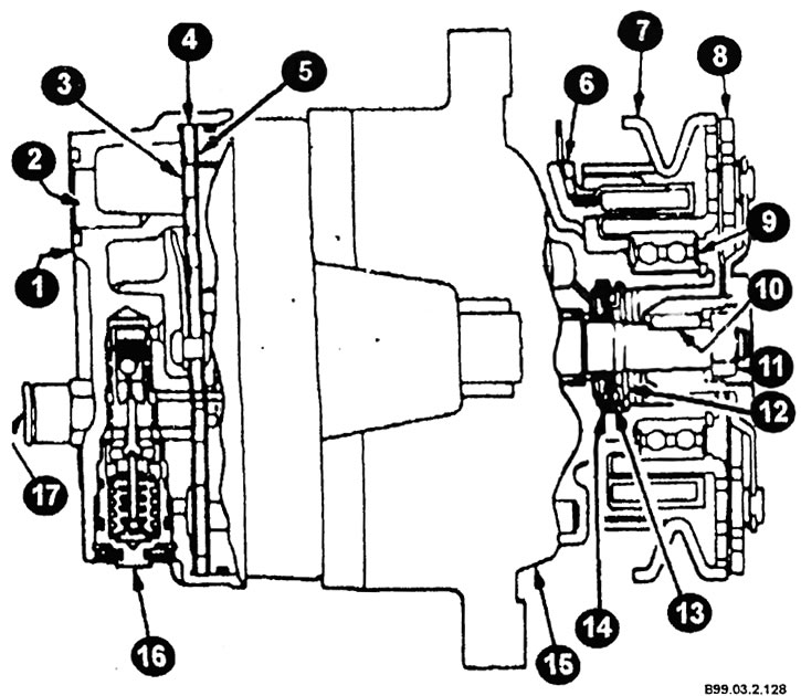
Compressor cross section
1 - back part; 2 - suction hole; 3 - gasket on the back; 4 - valve plate; 5 - tongue plate; 6 - coupling winding; 7 - pulley; 8 - leading disk; 9 - pulley bearing; 10 - shaft key; 11 - shaft nut; 12 - Front gasket holder; 13 - front gasket; 14 - Front gasket sealing ring; 15 - front part; 16 - compressor control valve; 17 - high pressure relief valve.
There are different types of compressors used in cars. The basic methods for carrying out major repairs on all compressors remain the same.
When performing maintenance, do not allow contamination or foreign objects to enter/or into the compressor parts and system. Before any repair or before removing the compressor, wipe the compressor connectors and its exterior. All compressor parts must be kept clean at all times, and those parts that are to be reinstalled must be wiped with trichloroethane, gasoline solvent, kerosene or a similar solvent, and then dried with dry air. Use only lint-free and fluff-free material for wiping.
When you remove the compressor from the machine for maintenance, the remaining oil in the compressor must be pumped out and measured. This must then be discarded and new 525 grade cooling oil added to the compressor.
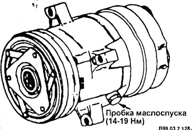
Job Description
The main mechanism of the compressor is a swash plate with a variable angle, which has five cylinders located along the axis. The compressor feed is controlled by a regulating valve, controlled by a corrugated membrane, located at the rear of the compressor, where its suction pressure is measured. The angle of the swash plate and the compressor feed are adjusted depending on the pressure difference in the engine crankcase and in the suction manifold. If the consumption of conditioned air is high, the suction pressure will be higher than the control point, the gas coming from the crankcase to the manifold will be released through the valve, there will be no pressure difference in the engine crankcase and in the suction manifold, and then the working volume of the compressor will be maximum. If the load on the air conditioning system is lower and the suction pressure reaches the control point, then the exhaust gas will go through the valve into the engine crankcase and the passage from the crankcase to the suction chamber will be closed.
The angle of the disc depends on the force balance on the five pistons. A slight increase in the pressure difference in the engine crankcase and in the intake manifold creates a resultant force on the pistons, which sets them in motion around the axis of rotation of the inclined disc, which reduces the angle of the disc. The compressor is equipped with a unique lubrication system. The oil flowing out of the crankcase goes through a rotating inclined disc to lubricate the bearing of this disc. During rotation, some of the oil is separated from the general flow and again directed to the crankcase, where the compressor mechanism is lubricated.
Oil may accumulate in the crankcase. Therefore, when replacing a compressor, it is important to pump out the oil from the crankcase of the old compressor through the drain hole and measure it (after measuring, throw away the old oil).
All compressors supplied for replacement have oil pumped into the crankcases; this oil needs to be pumped out and saved. Then replace the oil in the same amount that was measured on the old compressor.