



Contents: Duty cycle ⤓ Temperature control ⤓
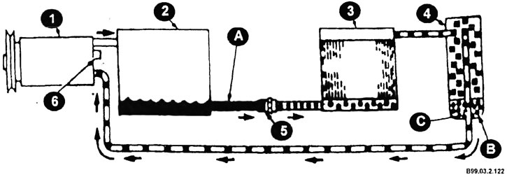
Air conditioning system operation diagram
1 - compressor; 2 - capacitor; 3 - evaporator; 4 - battery; 5 - expansion pipe (outlet pipe); 6 - bypass valve; A - liquid refrigerant; B - dehumidifier; C - channel for draining oil leaks.
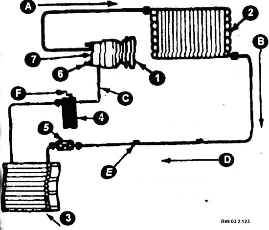
Functional units of the air conditioning system
A - discharge line - hot, high pressure steam; B - refrigerant flow; C - suction line - cold, low pressure steam; D - liquid pipeline - warm, liquid under high pressure; E - high pressure side working fitting; F - low pressure side working fitting; 1 - compressor; 2 - capacitor; 3 - evaporator; 4 - battery; 5 - expansion tube - outlet; 6 - bypass valve; 7 - low pressure switch.
Duty cycle
The circulation of the refrigerant is carried out according to the standard scheme. The compressor forces the refrigerant vapors into the condenser, where they condense with the release of heat to the condenser walls. From the condenser, the liquid refrigerant flows into the reservoir, from where it enters the evaporator under the action of the vacuum created by the compressor. Evaporating, the refrigerant lowers the temperature of the evaporator walls. The refrigerant vapors go back to the compressor. The flow of refrigerant through the evaporator is regulated by the expansion valve located in the evaporator body.
Temperature control
The compressor operates intermittently, maintaining the evaporator temperature within a certain range. When the temperature drops below the set value, the thermostat stops the compressor. When the temperature rises, the thermostat turns the compressor on again.