



Engine with MPI injection system
- Disconnect the two-pin connector from the ignition distributor and insert a special connector between the disconnected parts of the connector, thus all contacts of the connector will be connected.
- Connect the control tachometer to contact 12 of the connector (Fig. 19.67).
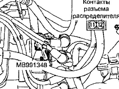
Fig. 19.67. Location of ignition distributor connector contacts
- Start the engine and, by varying the engine crankshaft speed, compare the tachometer readings with the readings of an external high-quality tachometer.
Standard values:
- 700 min⁻¹: ±100 min⁻¹
- 3,000 min⁻¹: ±150 min⁻¹
- 5,000 min⁻¹: ±250 min⁻¹
- 6,000 min⁻¹: ±300 min⁻¹
Engine with GDI injection system
- Using a paper clip, connect an external high-quality tachometer to the engine speed sensor connector terminals on the wiring harness side (Fig. 19.68).
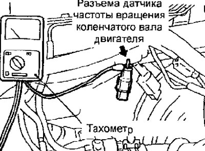
Fig. 19.68. Connecting an external tachometer to the wiring harness connector contacts
- Start the engine and, changing the frequency, compare the tachometer readings with the readings of an external high-quality tachometer.
Standard values:
- 700 min⁻¹: ±100 min⁻¹
- 3,000 min⁻¹: +225 min⁻¹, -100 min⁻¹
- 5,000 min⁻¹: +325 min⁻¹, -125 min⁻¹
- 7,000 min⁻¹: +400 min⁻¹, -100 min⁻¹
Diesel engine
- Using a paper clip, connect an external high-quality tachometer to the engine speed sensor connector terminals on the wiring harness side (Fig. 19.69).
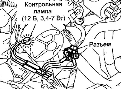
Fig. 19.69. Connecting an external tachometer to the contacts of the diesel engine wiring harness connector
- Start the engine and, by changing the engine crankshaft speed, compare the tachometer readings with the readings of the external tachometer.
Standard values:
- 700 min⁻¹: ±120 min⁻¹
- 2,000 min⁻¹: -175 min⁻¹, + 225 min⁻¹
- 3,000 min⁻¹: -175 min⁻¹, + 300 min⁻¹
- 4,000 min⁻¹: - 225 min⁻¹, + 375 min⁻¹
- 5,000 min⁻¹: - 225 min⁻¹, + 425 min⁻¹
- 6,000 min⁻¹: - 225 min⁻¹, + 475 min⁻¹
[The article is reprinted from a web resource: MITSUBISHIMAN]