



Contents: Engine oil ⤓ Engine coolant ⤓ Windshield Washer Fluid ⤓ Battery electrolyte ⤓ Hydraulic fluid for brake and clutch…⤓ Power steering fluid ⤓ Manual transmission oil ⤓ ATF ⤓ Checking the Transfer Case…⤓ Rear Axle Differential Lubrication…⤓
Note: There are also some special maintenance procedures below that require additional fluid level checks. Check underneath your vehicle regularly for signs of developing fluid leaks.
Checking the levels of the main working fluids (engine oil, coolant, windshield washer fluid, battery electrolyte, power steering fluid) should be done on a regular basis, at least once a month or every 5,000 km. The rest - in accordance with the maintenance schedule (see Section Schedule of current maintenance of Mitsubishi Galant/Mirage/Diamante cars).
Various fluids act as working fluids in lubrication, cooling, braking, clutch, heating and air conditioning, windshield washing, etc. systems. Since all fluids are subject to liquefaction and wear over time, and also gradually become contaminated during normal system operation, it is necessary to periodically replace them completely. Before adjusting the level or replacing, check out the list of recommended fluids for use in your vehicle.
Note: When checking fluid levels, the vehicle should be parked on a level, horizontal surface, preferably with a hard surface.
Engine oil
1. The engine oil level is checked using a dipstick inserted into the guide tube and lowered into the engine to the bottom of the oil pan. The location of the dipstick is shown in the illustrations showing the placement of components in the engine compartment of the vehicle and placed at the beginning of this Chapter.
2. The oil level should be checked before the first trip of the day, or about 15 minutes after the engine has been turned off. If the check is performed immediately after the engine has been turned off, the results will not adequately reflect the situation, since some of the oil will be distributed throughout the internal galleries and components of the engine.
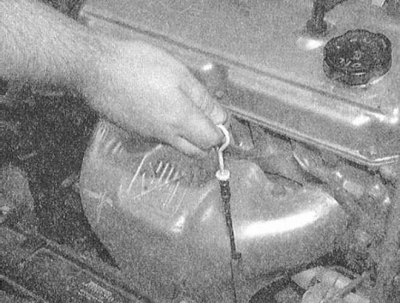
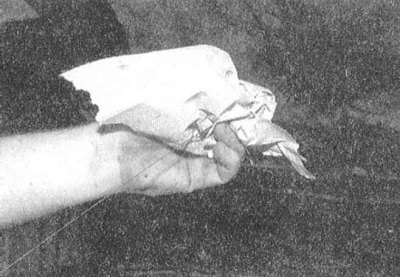
3. Remove the dipstick from the guide tube and wipe the blade dry with a clean rag or paper towel. Insert the dipstick back into the tube until it stops, then remove it again. Inspect the dipstick blade and estimate the size of the area wetted with oil. The oil level should be between the upper and lower marks on the dipstick blade. If necessary, add the appropriate amount of oil of the required grade to the engine.
 | 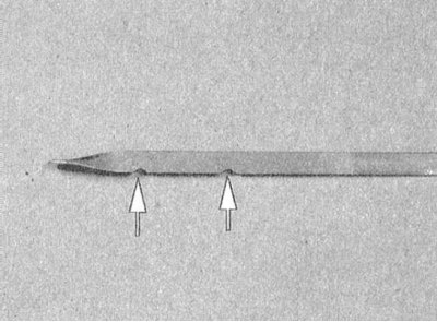 |
4. To raise the level from the lower (MIN) mark on the dipstick to the upper (MAX) mark, slightly less than one liter of oil is required. Lowering the level beyond the lower limit of the permissible range leads to the development of oil starvation of the engine, which is fraught with serious mechanical damage to the latter. Also try not to overfill the oil above the upper mark, as this can lead to spark plugs being thrown or failure of the power unit seals due to excessive pressure increase.
5. To fill the engine with oil, remove the threaded filler cap. To avoid splashing oil when pouring it into the engine, use a funnel or a long-nosed oiler. After filling the engine with oil, screw on and tighten the filler cap securely, then start the engine and carefully inspect the drain plug and the surface of the oil filter mating with the block for signs of leaks. Turn off the engine, wait about 15 minutes for the oil to drain into the pan, then check its level again.
6. Checking the engine oil level is an important preventive maintenance procedure for the engine. A constant decrease in the level indicates the presence of oil leaks due to failure of seals, damage to sealing gaskets, wear of piston rings or valve guides. If the oil is milky in color or consistency, or if there are drops of water in it, this indicates possible damage to the cylinder head gasket, or the formation of cracks in the body of the head(s) or block. The check must be done without delay. When measuring the oil level, always also check its condition. Use your thumb and forefinger to remove traces of oil from the dipstick blade - if there are small metal particles in it, the oil must be replaced (see Section Changing engine oil and oil filter).
Engine coolant
Warning! Do not allow antifreeze to come into contact with exposed areas of the body or painted surfaces of the vehicle. Wash away accidental splashes immediately with plenty of water. Remember that antifreeze is a highly toxic liquid and its ingestion, even in small quantities, can have the most serious consequences, including death. Never leave antifreeze stored in a loosely closed container; immediately collect any coolant spilled on the floor. Remember that the sweet smell of antifreeze can attract the attention of children and animals. Consult with local authorities about methods of disposal of used coolant - in many regions of the world, special collection points for various types of waste have been set up. Never pour old coolant into the sewer or onto the ground!
Note: Non-toxic grades of antifreeze have been developed in recent years, but they must still be disposed of in an orderly manner.
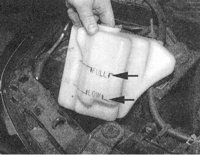
1. All models of cars described in this Manual are equipped with a compensating cooling system operating under excess pressure. The expansion tank of the cooling system, made of translucent plastic, is located in the front corner of the engine compartment close to the battery and is connected by an overflow hose to the base of the radiator filler neck. When the engine warms up, the coolant expands, and its excess flows through the valve mounted in the radiator filler cap into the expansion tank. As the liquid cools, it returns through the hose back to the radiator, which allows its level in the system to be constantly maintained at the normal level.
Caution! Never remove the radiator filler neck/expansion tank cap when the engine is hot!
2. The coolant level in the expansion tank is checked regularly and should be maintained between the FULL and LOW marks on the glass of the translucent plastic reservoir. It should be remembered that the coolant level depends on its temperature, so when cold it should be only slightly above the lower (LOW) mark, and after the engine warms up, it should rise to the FULL mark. If necessary, make the appropriate adjustment by adding the required amount of fresh mixture to the tank.
Attention! To adjust the fluid level, use only the required mixture of ethylene glycol and distilled water (approximately 50/50). Remember that frequent use of plain water for this purpose leads to gradual dilution of the antifreeze and the loss of frost resistance and anti-corrosion properties by the mixture. You should also not overuse various types of additives.
3. A constant drop in coolant level usually indicates that there are developing leaks in the system. Check the radiator, connecting hoses, filler cap, drain plugs and water pump housing for signs of leaks. If no signs of leaks can be found, the radiator cap should be pressure tested in a car service workshop.
Caution! Never remove the radiator/expansion tank cap when the engine is hot!
4. If you need to remove the radiator cap, wait until the engine has cooled down completely, then wrap the neck with a thick layer of rags and slowly unscrew the cap to the first stop. If steam is released, allow the engine to cool down a little more, and only then remove the cap completely.
5. In addition to the level, always check the condition of the coolant - it should be relatively clear. If the coolant is a reddish-brown rust color, the cooling system should be drained, flushed and filled with a fresh mixture of antifreeze and water. Even if the liquid does not change in appearance, the corrosion inhibitors it contains are subject to wear over time, so the coolant should be replaced regularly in accordance with the vehicle's routine maintenance schedule (see Section Schedule of current maintenance of Mitsubishi Galant/Mirage/Diamante cars).
6. Try not to allow antifreeze to come into contact with exposed skin or painted surfaces of body components. Wash off any accidental splashes immediately with plenty of water.
Windshield Washer Fluid
Windshield washer fluid is poured into a special plastic reservoir located in the front corner of the car's engine compartment, opposite the corner where the battery and the expansion tank of the cooling system are located. In regions with a moderate climate, clean water can be used as a windshield washer fluid, but the reservoir should not be filled more than 2/3 full to compensate for the expansion of water when it freezes during frosts. When operating the car in severe climatic conditions, use only patented windshield wipers that provide an appropriate decrease in the freezing point of the liquid. To avoid freezing of the glass when washing in cold weather, preheat it by blowing air passed through the heater heat exchanger
Attention! The rules for mixing the mixture are usually printed on the container label. Never use the antifreeze used in the cooling system to add to the windshield washer fluid - the latter is aggressive towards the paintwork of the body panels!
Battery electrolyte
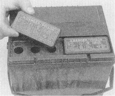
The vehicles covered by this Manual are equipped with a sealed maintenance-free battery, the casing of which only has ventilation holes. The battery casing may be made of translucent plastic - in this case, the electrolyte level in its cells can be monitored to obtain indirect information about the proper functioning of the charging system and the current state of the battery. If, during the operation of the vehicle, the battery was replaced for any reason with a conventional (serviceable type) battery, the electrolyte level in its cells should be checked from time to time by removing the upper control/filler plugs. The electrolyte level should be monitored especially carefully during the warm season. Only distilled water should be used to adjust the electrolyte level.
Hydraulic fluid for brake and clutch systems
1. The brake master cylinder (BMC) is mounted on the brake booster servo unit. The clutch hydraulic cylinder is used on models with a manual transmission and is mounted on the rear bulkhead of the engine compartment next to the BMC (the location of the reservoirs of both cylinders is shown in the accompanying illustrations explaining the location of components in the engine compartments of the models under consideration at the beginning of this Chapter).
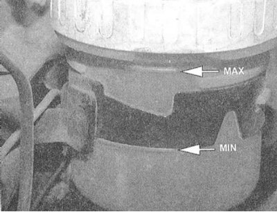
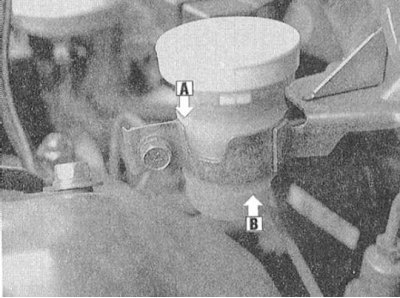
2. The fluid level inside the master cylinder and clutch drive reservoirs is clearly visible through the translucent walls of the latter and should be maintained between the MIN and MAX marks, not reaching the top by 8÷9 mm.
 |  |
3. If it is necessary to adjust the fluid level, carefully wipe the cap of the corresponding reservoir and the area around it with a clean cloth to prevent dirt from getting into the hydraulic system.
4. When pouring fluid into the reservoir, make sure that it does not splash onto the surrounding painted surfaces of body parts. Add only the fluid of the grade specified by the regulatory requirements to each of the systems (see Specifications at the beginning of this Chapter), - mixing two liquids of different types is in no way permissible and may lead to failure of the corresponding system!
Warning! Brake fluid is extremely chemically aggressive - do not allow it to come into contact with your eyes or paint on body panels! Do not add hydraulic fluid to the system that has been standing for more than one year or that has been stored in a loosely closed container. Remember that brake fluid is very hygroscopic, i.e. it has the ability to absorb moisture from the air, which can dangerously reduce the efficiency of the brake system!
5. During the level adjustment stage, the condition of the fluid and the inner walls of the tank should also be carefully checked. If mud deposits, solid foreign particles or water droplets are detected, the system should be emptied and filled with fresh hydraulic fluid (see Chapters Clutch and transmission line и Brake system).
6. Once the tank is filled to the required level, place the lid on it tightly.
7. Remember that the hydraulic fluid level in the master cylinder reservoir gradually drops as the friction linings of the brake shoes are applied, but this decrease is always very slight. If the fluid has to be topped up too often, then there is a leak in the system, the source of which must be identified without delay and the cause eliminated - carefully inspect all brake lines and their nipple connections, including calipers, wheel cylinders and the vacuum booster servo (for more details, see Section Checking the proper functioning of the brake booster). A drop in the fluid level in the clutch hydraulic drive reservoir indicates the development of leaks in the tract, including the slave cylinder (see Chapter Clutch and transmission line).
8. If, during the check of the fluid level in the master cylinders, it is revealed that its reservoir is almost empty, the corresponding system must be completely bled (see Chapter Clutch and transmission line or Brake system).
Power steering fluid
1. The power steering fluid reservoir is located in the front corner of the engine compartment behind the windshield washer fluid reservoir (see the accompanying illustrations explaining the location of components in the engine compartments of the models under consideration at the beginning of this Chapter).
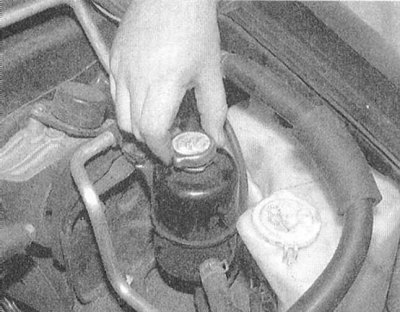
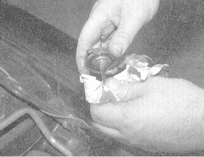
2. The tank lid is equipped with a built-in measuring probe. The checking procedure is standard for all measurements using probes.
 | 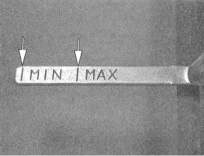 |
3. Try not to allow the liquid level to go beyond the lower limit of the permissible range.
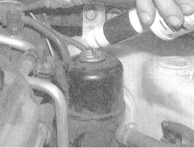
4. If necessary, make the appropriate adjustment to the level by adding the required grade of hydraulic fluid into the reservoir neck.
5. If the need to adjust the fluid level occurs regularly and frequently, check the steering pump, rack and pinion housing, as well as all connecting lines of the hydraulic system tract and their fittings for signs of leaks.
Manual transmission oil
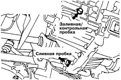
1. The manual transmission housing is not equipped with a dipstick. Jack up the car and place it on supports. The transmission oil level in the gearbox is checked by unscrewing the control/filler plug from the side wall of the manual transmission housing. Find the plug and carefully wipe the surrounding surface of the gearbox housing with a clean rag. Using a socket or open-end wrench, unscrew the plug - the transmission oil level in the housing should reach the lower edge of the control/filler hole, otherwise it is necessary to make the appropriate adjustment. If the car is raised above the ground in order to provide access to the manual transmission housing, before climbing under it, make sure that the supports are securely fastened.
Attention! The car must be installed strictly horizontally!
 | 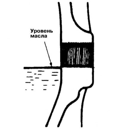 |
2. Using a funnel with a suitable adapter, pour the required amount of fresh transmission oil into the manual transmission housing. Continue pouring oil until it begins to overflow the lower edge of the filler/inspection hole.
3. Screw the carefully wiped plug back into place and tighten it securely. Perform a short road test of the car, after which make sure that there are no signs of oil leakage through the plug.
ATF
1. The correct ATF level is one of the critical operating parameters of models equipped with AT. An excessive drop in the ATF level can lead to slippage of the rotation converter, while an excessive amount of fluid leads to its foaming, leakage and is fraught with transmission failure.
2. The ATF level should be checked when the transmission is warmed up to normal operating temperature (15÷20 km, 72÷80°C).
Caution! Do not check the ATF level immediately after driving the vehicle at high speeds, in hot urban conditions, or after towing a trailer - allow the fluid to cool down for about 30 minutes first!
3. Park the car on a flat, horizontal surface with a hard surface, firmly set the parking brake. If the engine is cold, start it and warm it up to normal operating temperature at idle speed. With the engine running, depress the foot brake pedal and move the AT selector lever through all positions in turn, finally returning it to the "P" position.
The original can be found on the website: MITSUBISHIMAN.ru
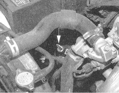
4. Without stopping the engine, remove the dipstick from the guide tube. Use your fingers to remove traces of ATF from the dipstick blade and assess its condition by touch.
5. Wipe the blade thoroughly with a clean cloth and insert the probe back into the guide tube, firmly fitting the cap onto the neck.
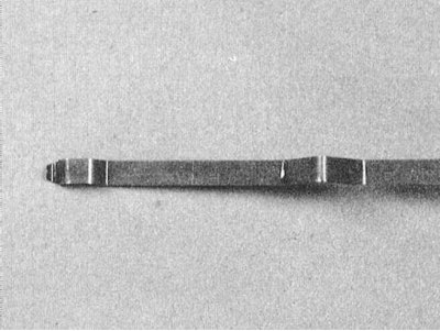
6. Remove the dipstick from the filler neck again and determine the ATF level in the transmission housing by the length of the wetted section of the blade. If necessary, make the appropriate adjustment by adding the required grade of fluid to the transmission through a funnel - pour ATF directly into the filler neck of the dipstick guide tube.
7. To raise the ATF level from the lower limit of the dipstick's working range to the upper limit, approximately 0.6 l of fluid is required - add ATF in small portions in several steps, checking the level each time.
8. At the same time as the level, the condition of the ATF should also be checked. If the fluid wetting the end of the dipstick blade has a dark reddish-brown tint or smells of burning, the ATF should be replaced (see Section Replacement of ATF of automatic transmission and differential of main gear, checking of condition and maintenance of AT filter). If you are not sure that the condition of the transmission fluid is correct, compare it by color and smell with fresh ATF.
Checking the Transfer Case Lubrication Level (Galant 4WD Only)
1. Park the car on a level, horizontal surface, if possible with a hard surface. Set the parking brake, on models with automatic transmission, move the selector lever to the "P" position.
2. Before starting the check, inspect the transfer case housing for signs of developing leaks. The lubricant level in the transfer case on all-wheel drive models should reach the lower edge of the inspection/filler hole on the rear side of its housing. To check, insert your finger into the hole. At the same time, assess the condition of the oil poured into the box by touch.
3. If necessary, make the appropriate adjustments by adding the required amount of oil through the filler hole - use a funnel or a hand pump.
4. Make sure the plug is tightened securely.
Rear Axle Differential Lubrication (Galant AWD Only)
1. Park the car on a level, horizontal surface, if possible with a hard surface. Set the parking brake, on models with automatic transmission, move the selector lever to the "P" position.
2. The lubricant level in the differential should also reach the lower edge of the inspection/filler hole. To check, insert your finger into the hole. At the same time, assess the condition of the oil poured into the box by touch.
3. If necessary, make the appropriate adjustments by adding the required amount of oil through the filler hole - use a funnel or a hand pump.
4. Make sure the plug is tightened securely.