
English Русский
Български
Беларускі
Український
Српски
Hrvatski
Română
Polski
Slovenský
Magyar
Articles Bookmark Contacts Sitemap   
Company Audi Company Ford Company Hyundai Company Kia Company Mazda Company Mercedes-Benz Company Nissan
MitsubishiMan.ru


Home Colt Lancer Galant L200 Outlander Pajero Others
Carisma (1995-2004) Space Star (1998-2005)

Ignition switch (Mitsubishi Space Star)

  • Home
  • Mitsubishi
  • Space Star (1998-2005)
  • Electrical equipment
  • Equipment and devices
  • Ignition switch
0
Contents: Removal ⤓ Examination ⤓ Installation ⤓


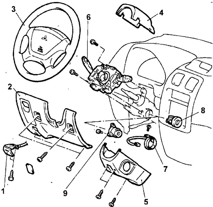
Fig. 19.60. Ignition switch: 1 - hood release handle; 2 - lower panel on the driver's side; 3 - steering wheel; 4 - Upper steering column cover; 5 - lower steering column cover; 6 - multifunctional steering column switch, 7 - ignition switch ring antenna; 8 - ignition switch; 9 - steering column lock


Removal


  • Disconnect the negative battery cable and isolate it, then wait 60 seconds for the capacitor to discharge. Otherwise, the airbag may deploy unexpectedly, which may cause personal injury.
  • Remove the screws, disconnect the cable and remove the hood release handle.
  • Remove the screws and remove the lower panel from the driver's side.
  • On a vehicle without SRS, remove the horn switch cover. On a vehicle with SRS, remove the airbag.
  • Loosen the steering wheel mounting nut. Apply alignment marks to the end of the steering shaft and the steering wheel and remove the steering wheel with a puller.
  • Remove the screws and remove the upper and lower steering column covers.
  • Disconnect the electrical connectors from the multifunction switch. Remove the three bolts and remove the multifunction switch.
  • In the reverse order to that shown in Figure 19.61, unscrew the screws securing the spiral wire.
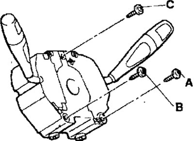


Fig. 19.61. Sequence of tightening the screws for fastening the spiral wire


  • Disconnect the electrical connector and remove the ignition switch ring antenna.
  • Insert the key into the ignition switch and turn it to the ACC position.
  • Using a small screwdriver, press the pin and pull the cylinder out of the ignition switch (Fig. 19.62).
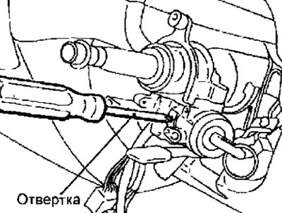


Fig. 19.62. Using a screwdriver to push in the pin before removing the ignition switch cylinder

  • If it is necessary to remove the steering column lock, use a hammer and chisel to break the side walls of the holes in which the heads of the bolts for fastening the steering column lock bracket are recessed (Fig. 19.63). Use a hacksaw for metal to cut grooves in the heads of the cut-off bolts for fastening the steering column lock bracket. Use a flat-blade screwdriver to unscrew the bolts and remove the steering column lock bracket.
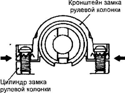


Fig. 19.63. The location of the destruction of the side walls of the holes in which the heads of the bolts for fastening the steering column lock bracket are recessed


Examination


  • Remove the screws and remove the upper and lower steering column covers.
  • Disconnect the connector from the ignition switch (Fig. 19.64).
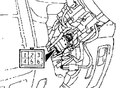


Fig. 19.64. Ignition switch connector pin location


The article was taken from the website [www.mitsubishiman.ru]
  • By turning the ignition key to different positions, check the electrical circuits of the ignition switch.
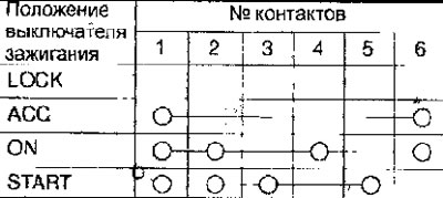

  • Use an ohmmeter to check the electrical circuit between the contacts of the ignition switch ring antenna connector (Fig. 19.65). The circuit should be closed.
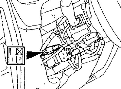


Fig. 19.65. Location of contacts on the ignition switch ring antenna connector


Installation


  • Installation is carried out in the reverse order of removal, taking into account the following.
  • Install the spiral wire and secure with screws, tightening them in the sequence shown in Figure 19.61.
  • When installing the lock and steering column lock bracket into the steering column, temporarily install the lock into the steering column protrusion.
  • Check the operation of the steering column lock, and then tighten the special bolts until the bolt heads are sheared. When installing the steering column lock, it is necessary to use a new steering column lock bracket and special bolts.
  • After setting the wheels to the straight-ahead position, check the position of the steering wheel.
This article is available at: russian, bulgarian, belarusian, ukrainian, serbian, croatian, romanian, polish, slovak, hungarian
This article was reviewed by: Miroslav Rakov
Share with friends:
◀ Previous
Space Star: Equipment and devices
Next ▶

 
Checking the speedometer
Checking the tachometer
Checking the fuel level sensor
Checking the coolant temperature sensor
Instrument cluster
Similar materials for other Mitsubishi models

➤ Ignition switch — removal and installation Mitsubishi Colt 2 and 3 (1983-1993)
➤ Interior lighting, luggage compartment lighting and… Mitsubishi Lancer 9 (2000-2007, petrol)
➤ Ignition switch Mitsubishi Galant 6 and 7 (1987-1998)
➤ Interior lighting and ignition switch illumination Mitsubishi L200 4 (2005-2014, diesel)
➤ Interior lighting lamps, ignition switch illumination Mitsubishi Outlander 1 (2003-2008)
➤ Ignition switch — general description Mitsubishi Pajero 1 and 2 (1982-1999)
Link in different formats to this article
Comments and feedback from visitors
No comments yet


Add up two numbers 35 + 24


Carisma (1995-2004) 
  • General information
  • User manual
  • Maintenance
  • Power unit
  • Petrol engines 4G9
  • Diesel engines FBQT
  • Diesel engines F9Q
  • Cooling system
  • Injection system (MPI)
  • Injection system (GDI)
  • Engine electrical equipment
  • Transmission
  • Clutch
  • Mechanical gearbox
  • Automatic gearbox
  • Chassis and running gear
  • Steering
  • Brake system
  • Front suspension and shafts
  • Rear suspension
  • Body and interior
  • Exterior (external elements)
  • Interior (internal elements)
  • Doors, locks and windows
  • Air conditioner
  • Electrical equipment
  • Equipment and devices
  • Headlights and lighting
  • Electrical circuits
Space Star (1998-2005) 
  • General information
  • User manual
  • Maintenance
  • Power unit
  • Petrol engines 4G9
  • Petrol engines 4G1
  • Diesel engines F9Q1
  • Cooling system
  • Fuel injection system GDI
  • Fuel injection system MPI
  • Diesel supply system F9Q1
  • Ignition system
  • Diesel preheating
  • Transmission
  • Clutch
  • Mechanical gearbox
  • Automatic gearbox
  • Chassis and running gear
  • Suspension and drive shafts
  • Brake system
  • Steering
  • Body and interior
  • Exterior (external elements)
  • Interior (internal elements)
  • Doors, locks and windows
  • Heating and air conditioning
  • Electrical equipment
  • Power devices
  • Equipment and devices
MitsubishiMan.ru © 2018–2026 • Mobile version • Articles about Mitsubishi • Contacts • Sitemap: EN BG BY UA RS HR RO PL SK HU • Site search • Bookmark
Colt 2 and 3 (1983-1993) · Colt 4 and 5 (1991-2003) · Colt 5 (1995-2003) · Lancer 3 and 5 (1984-1992) · Lancer 9 (2000-2007) · Galant 5 (1983-1989) · Galant 6 and 7 (1987-1998) · L200 4 (2005-2014) · Outlander 1 (2003-2008) · Pajero 1 and 2 (1982-1999) · Pajero 4 (2006-2021) · Carisma (1995-2004) · Space Star (1998-2005) ·
This resource sets cookies 🍪 to avoid bothering you with repeated data entry.