Contents: Removal ⤓ Checking the headlight relay and…⤓ Checking the conductivity of the…⤓ Checking the conductivity of the…⤓ Checking the headlight corrector ⤓ Resistance between connector…⤓
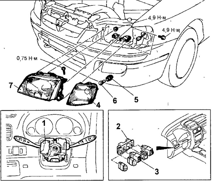
Fig. 19.80. Headlights and front direction indicators: 1 - Multifunctional steering column switch (with light and turn signal switch); 2 - decorative trim for switches; 3 - headlight corrector; 4 - front turn signal; 5 - cartridge; 6 - lamp; 7 - headlight
Warning: When servicing Supplemental Restraint System (SRS) components, care must be taken to avoid personal injury due to unauthorized deployment of the air bags.
Removal
- Disconnect the cable from the negative battery terminal.
- Remove the expansion tank of the cooling system (if replacing only the left headlight).
- Remove the multifunction steering column switch (see section "Steering").
- To remove the headlight range adjuster switch, use a screwdriver to lever off the switch trim, then disconnect the electrical connector, squeeze the latches and remove the headlight range adjuster.
- Insert a screwdriver as shown in Figure 19.81 and remove the screw securing the front turn signal. Pull the turn signal forward to remove it and disconnect the electrical connector from it.
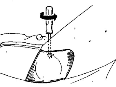
Fig. 19.81. Removing the front turn signal mounting screw
- Remove the headlight cover by turning it counterclockwise and disconnect the connectors.
- Loosen the nuts and bolts and remove the headlight.
- Checking the light switch
- Use an ohmmeter to check the conductivity between the connector contacts in different positions of the light switch (Fig. 19.82).
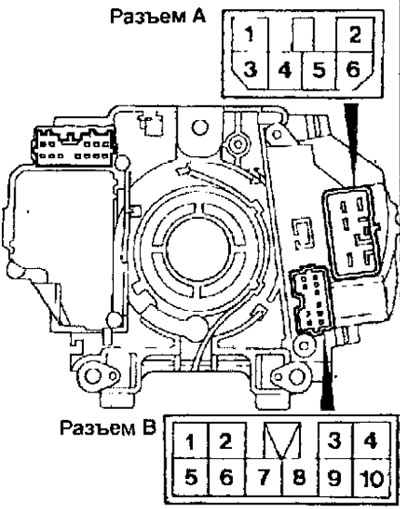
Fig. 19.82. Location of contacts of the multifunctional steering column switch
Checking the headlight relay and taillight relay
- Remove the headlight relay, the rear light relay and check the conductivity between the relay contacts (Fig. 19.83).
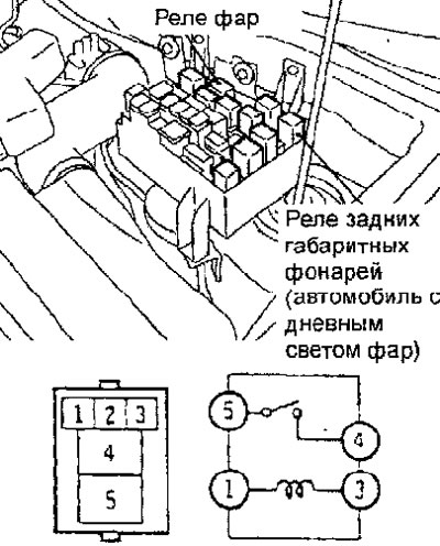
Fig. 19.83. Location of headlight relay and rear light relay
Checking the conductivity of the multi-function steering column switch
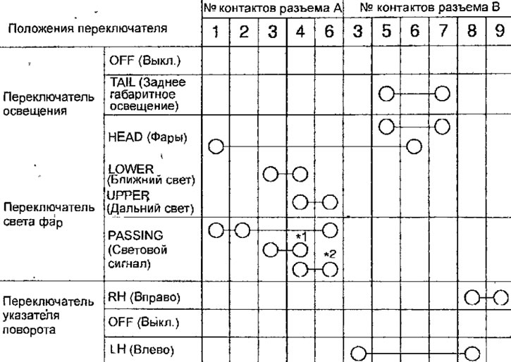
Note
- *1 means closed contacts when low beam is on (Lower);
- *2 means contacts are closed when the high beam is on (Upper).
Checking the conductivity of the multi-function steering column switch
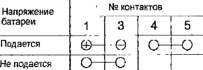
- If the conductivity is different from the required value, replace the relay.
Checking the headlight corrector
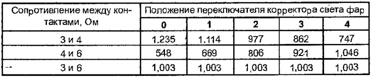
- Check the resistance between the contacts of the headlight corrector switch at different switch positions (see table and Fig. 19.84).
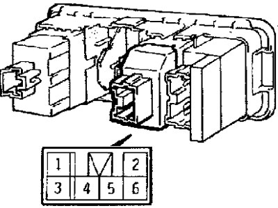
Fig. 19.84. Location of headlight corrector connector contacts
- If the resistance is different from the specified value, replace the switch.
Resistance between connector contacts at different positions of headlight range control switch