
General information
Several different types of hinges can be used to complete the drive shafts of the vehicles discussed in this Manual. The specific choice is determined by the engine displacement, transmission type, the position of the hinge on the shaft (indoor or outdoor) and even the position of the shaft itself on the car (right or left).
Before performing any kind of hinge maintenance (including replacement of the protective cover) design should be determined. First of all, you should pay attention to the identification number of the hinge assembly - the number is usually applied to the large end surface of the hinge, sometimes the marking can be stamped on the ends of the bandage tapes.
As mentioned above, several, namely, three types of drive shaft joints are used on the vehicles considered in this Guide, these are: Bearfield joints (BJ), tripod joints (TJ) and double compensation joints (DOJ).
Note. Bearfield joints are not subject to disassembly and, in case of failure, are replaced as an assembly.
An important operational parameter of hinges of all types is the distance between the shroud years of fastening the protective cover - excessive stretching of the cover or too loose fit can lead to cracks, loss of lubrication and ingress of dirt and moisture into the hinge assembly.
Note. For stuffing the hinges of the drive shafts, a special lubricant is used, which is required to be supplied complete with replaceable covers.
Double compensation hinges (DOJ)
Removing
1. DOJ joints differ from others in larger overall dimensions and are usually used as internal CV joints.
2. Remove the drive shaft from the vehicle (see Section Removal and installation of power shafts).
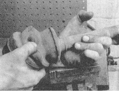
3. Assess the condition of the rubber protective boot.
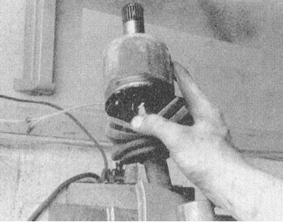
4. Snip the metal bands with side cutters and remove the protective cover from the outer clip (corps) hinge.
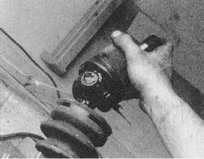
5. Locate and remove the large retaining ring at the base of the pivot assembly. Remove the outer casing (frame) hinge.
6. Remove the small circlip and remove the inner race complete with separator and balls. Thoroughly clean the removed assembly without disassembling it.
7. If the condition of the protective cover is found to be satisfactory and it is subject to further use, wipe the shaft trunnion and wrap the area equipped with splines with a protective layer of tape, then carefully remove the cover from the shaft.
8. If necessary, the protective cover of the outer BJ joint can also be removed at this stage.
Installation
1. Check the reliability of the protection of the splines of the shaft with adhesive tape.
2. Pack the protective cover of the hinge with special grease (the grease usually supplied with a new boot is divided into two equal parts, one of which goes to the stuffing of the hinge cavities, the second is pushed into the boot).
3. Fit the joint separator onto the shaft (smaller side of cage forward). Slightly tapping along the perimeter of the end surface with a hammer through a brass drift, gently tap the inner race of the assembly until it stops against the special hangers on the shaft trunnion. Filling the cavities of the components with grease, articulate the clip with the separator and fill the balls into the latter.
4. Also stuffed with grease, install the outer race (frame) hinge.
5. Pull the protective cover over the body of the hinge assembly (to equalize the pressure, pry off the edge of the cover with a blunt instrument and release air from under it) and secure it with new bandage tapes - make sure that the distance between the inner and outer tapes meets the regulatory requirements.
6. Install the shaft on the car (see Section Removal and installation of power shafts).
Other hinges
Removing
1. Disconnect the negative cable from the battery.
If the stereo system installed in the car is equipped with a security code, before disconnecting the battery, make sure that you have the correct combination to activate the audio system!
2. Remove the drive shaft (see Section Removal and installation of power shafts).
3. Assess the condition of the rubber protective boot.
4. Cut through the bandages with side cutters and remove the protective cover from the body of the hinge assembly.
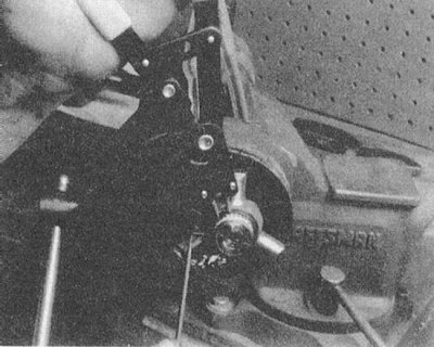
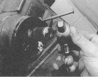
5. Remove the retaining ring and remove the triode spider assembly from the shaft stub.
Note. The tripod assembly cannot be disassembled and must be handled with care.
 |  |
6. If the condition of the protective cover is considered satisfactory and it is subject to further use, wipe the shaft pin and wrap the area equipped with splines with a protective layer of adhesive tape, then carefully remove the dynamic damper from the shaft (if any) and rubber case/covers.
Installation
1. Check the reliability of the protection of the splines of the shaft with adhesive tape.
2. Gently place boot (s) and dynamic damper onto the shaft in the appropriate order (if provided).
3. Install the tripod assembly and secure it with the retaining ring.
4. Stuff the internal cavity of the hinge with special grease from the repair kit (use about half of the lubricant supply on the hinge packing, the second half will be spent on filling the boot).
Try not to let grease get on the rubber elements of the dynamic damper assembly, if any!
5. After stuffing the boot with the remaining grease, pull it onto the hinge body (to equalize the pressure, pry off the edge of the cover with a blunt instrument and release air from under it) and secure with bandage tapes, - make sure that the distance between the inner and outer bands complies with the regulatory requirements.
6. Install the shaft on the car (see Section Removal and installation of power shafts) and connect the negative wire to the battery.