
Removing
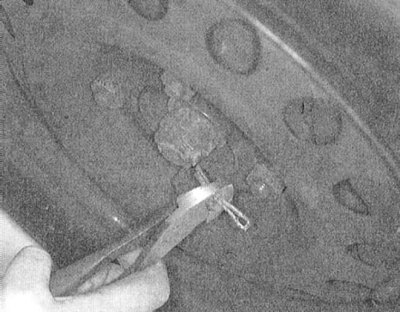
1. Without jacking up the vehicle, remove the cotter pins and loosen the front wheel hub nuts.
 |  |
2. Jack up the car and put it on stands.
3. On models equipped with ABS, remove the front wheel sensors.
4. On Active-ECS equipped models, loosen the union nut securing the air line to the top of the rack. Remove and discard the O-ring. Unscrew the mounting bolts and remove the system actuator from the top of the rack. Disconnect the wiring connected to the activator.
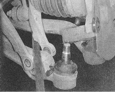
5. Release the ball bearings of the lower suspension arms and the tie rod ends from the steering knuckles.
 |  |
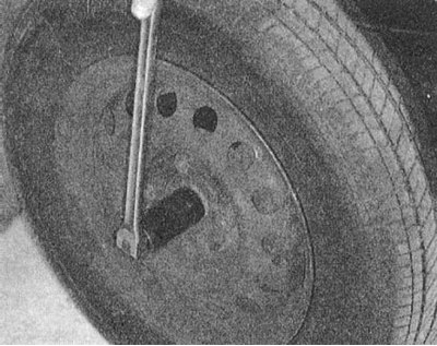
6. Give hub nuts and remove washers.
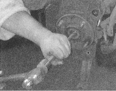
7. At removal of assembly of a two-section left power shaft turn out bolts of fastening of the central basic bearing and remove the washers placed under their heads. Using a puller installed on the outside of the hub assembly, squeeze the drive shaft trunnion out of the last (at the final stage, the trunnion is knocked out with a hammer. The shaft assembly is knocked out of the transmission differential using a soft-faced hammer.
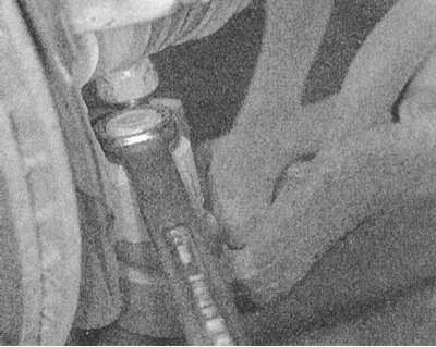
8. The assembly of a single-section right drive shaft is released from the transmission by prying it with a mount.
Attempts to pull the shaft out of the differential are fraught with failure of the inner CV joint!
Installation
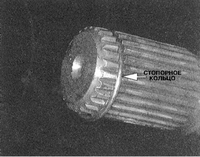
1. Replace the circlips on the inner trunnions of the drive shafts.
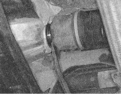
2. Thread the shafts into the transmission - make sure that the trunnions are fully seated.
3. Pulling the rack assembly outward, thread the outer trunnion of the corresponding drive shaft into the hub.
4. Screw in the bolts of the center bearing bracket and tighten them to the required torque (45 Nm).
5. Place a washer on the shaft stub (chamfered side out). Screw on the hub nut, however, do not tighten it completely yet.
5. Fit the ball joint into the steering knuckle assembly. Tighten the castle nut of the ball stud to the required torque (60÷72 Nm) and secure it with a new cotter pin.
6. Also fit the tie rod end into the steering knuckle assembly, the castellated nut of the ball joint is tightened with a force of 29 Nm and is also fixed with a new cotter pin.
7. On ABS equipped models, reinstall the wheel sensors.
8. On models with active suspension (Active-ECS) restore the original pneumatic line connection (don't forget to replace the o-ring) and attach the actuator activator to the top of the rack. Connect electrical wiring.
9. Proceeding in a similar manner, complete the installation of the second drive shaft.
10. Install the wheels and lower the vehicle to the ground.
11. Tighten the hub nuts to the required torque (145÷188 Nm) and secure with new cotter pins.