
Attention: general rules for replacing fuses and fuses are given in chapter "Manual".
Location of components
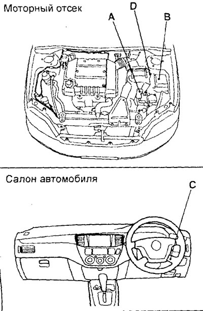
A - block of fusible inserts on the positive terminal of the battery, B - mounting block in the engine compartment, C - mounting block in the passenger compartment, D - additional mounting block in the engine compartment.
Note: the location and purpose of relays, fuses and fuses on models of different years of manufacture and in different configurations may differ slightly from those shown in the figures and tables.
Fusible links
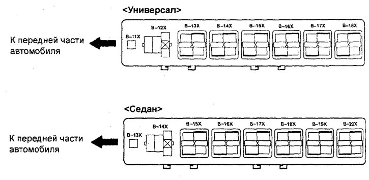
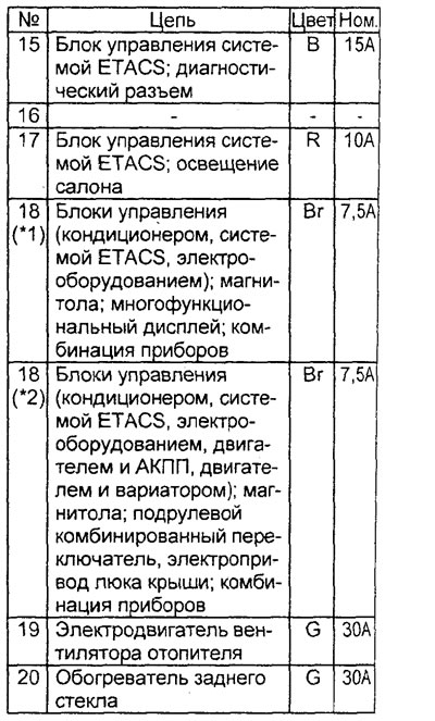
Mounting block in the engine compartment (except sedan models from 05.2001)
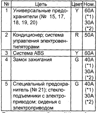
Note: in the table (*1) - station wagon models; (*2) - sedan models.
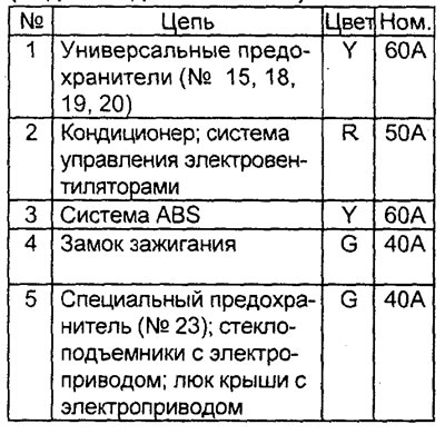
Mounting block in the engine compartment (sedan models from 05.2001)
Fusible block (except sedan models from 05.2001)
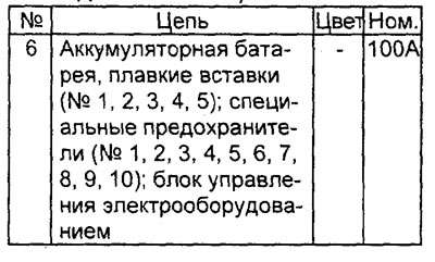
Fusible block (sedan models from 05.2001)
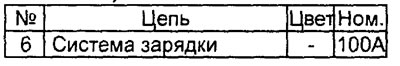
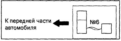
General view of the block of fusible inserts.
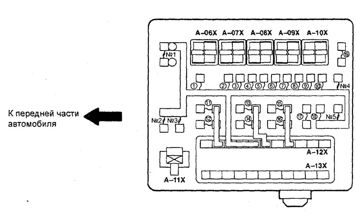
General view of the mounting block in the engine compartment.
General view of the additional mounting block in the engine compartment.
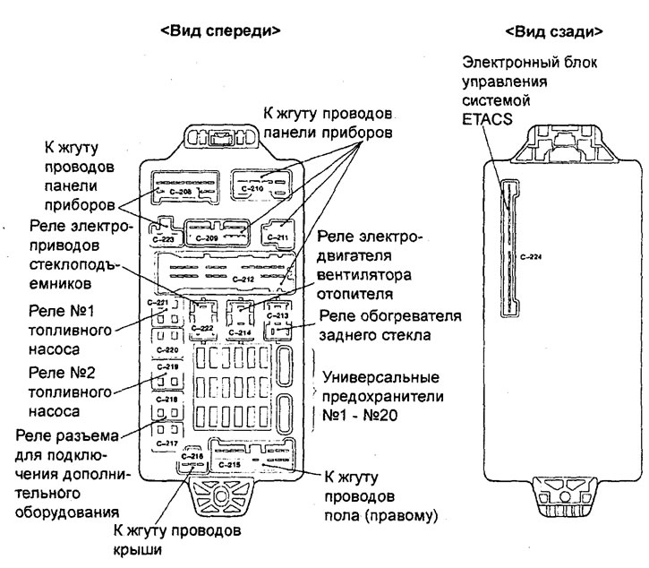
General view of the mounting block in the cabin.
Mounting block in the engine compartment.
Additional mounting block in the engine compartment (station wagon)
Additional mounting block in the engine compartment (sedan)
Special fuses
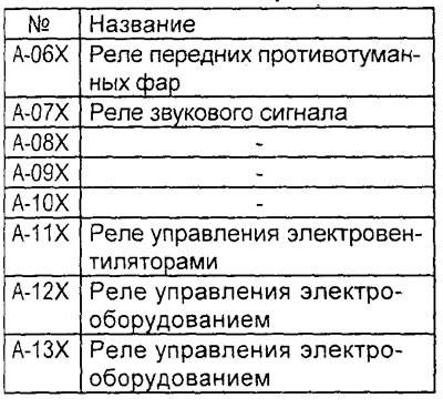
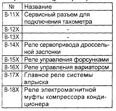
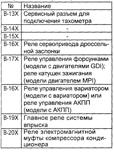
Mounting block in the engine compartment
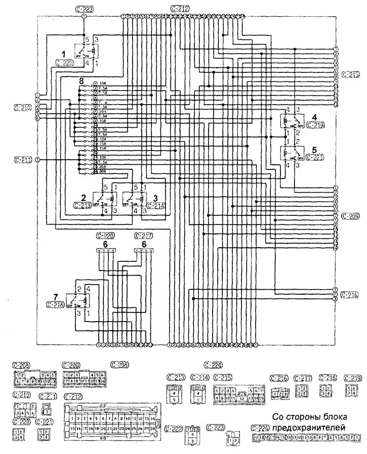
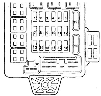
Internal circuits of the mounting block in the cabin. 1 - power window relay, 2 - rear window defroster relay, 3 - heater blower motor relay, 4 - fuel pump relay #2, 5 - fuel pump relay #1, 6 - not used, 7 - accessory connector relay, 8 - universal fuses.
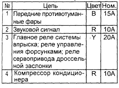
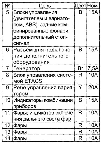
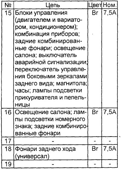
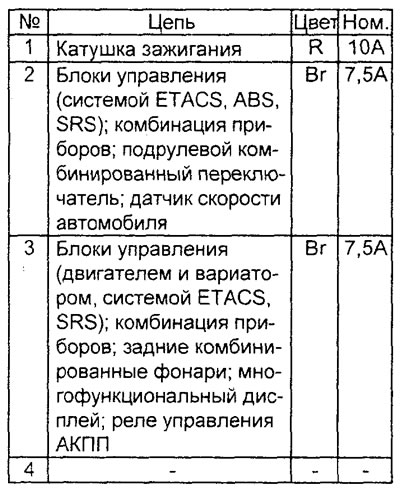
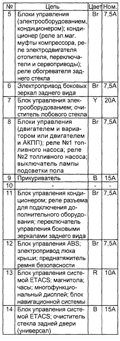
Mounting block in salon
Mounting block in salon (special fuses).
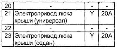
Universal fuses
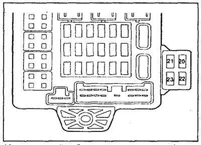
Mounting block in salon
Mounting block in salon (universal fuses).
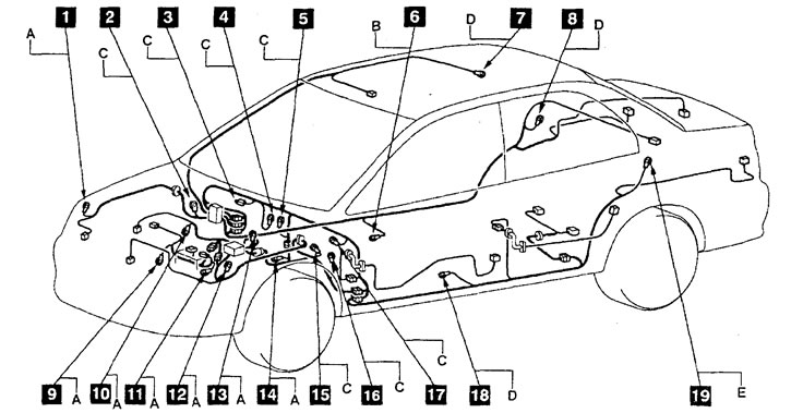
Location of connection points with "weight" and general wiring diagram (sedan).
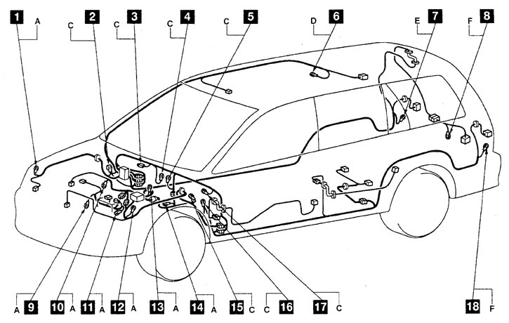
Location of connection points with "weight" and general wiring diagram (station wagon).