



Contents: How to use electrical equipment…⤓ Designations of connectors,…⤓ Connector markings ⤓ Wire marking ⤓ Table of designations of electrical…⤓ Color coding ⤓ Abbreviations ⤓
How to use electrical equipment diagrams
Each diagram represents a separate subsystem of electrical equipment from the fuse (or fuse link) to the "ground". To simplify the understanding of the diagram, the power source is shown at the top of the diagram, and the "ground" is at the bottom.
A: Indicates the power source.
B: Indicates the wiring connection point number for another system that has a connection with the system in question. Corresponds to the wiring connection point number shown on the target system diagram.
C: The name of the target system that has a connection with the system under consideration.
D: If there is no space next to the connector number on the diagram to place its image, then the connector number is placed in the symbol and the connector itself is placed in another place.
E: The "X" at the end of the connector number indicates that the connector connects to a central branching point (e.g. relay box, etc.).
F: When connecting single-pole connectors, the terminal number and connector number are omitted.
G: Indicates the operating conditions of the sensor (e.g. coolant temperature switch, etc.).
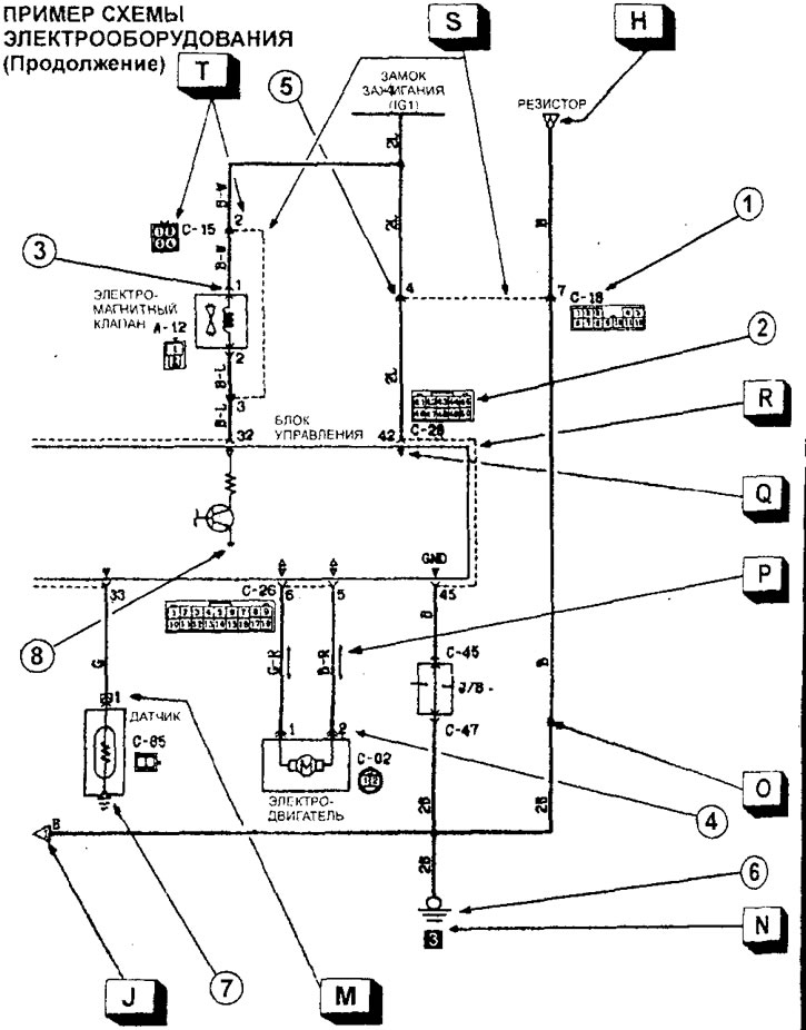
H: Indicates that the circuit continues at a point elsewhere on the diagram.
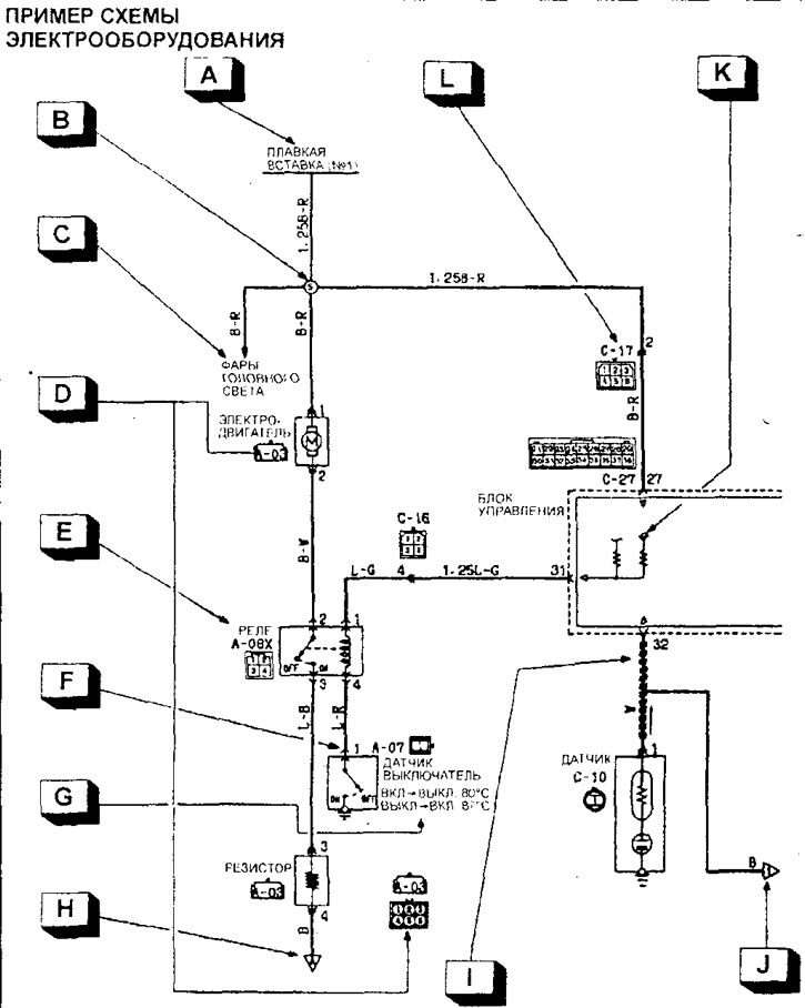
I: Indicates shielded wiring harness.
J: Indicates that the circuit continues on to the next part of the circuit diagram.
K: Indicates the power source in the control unit. If the voltage is not specified, it is assumed to be equal to the on-board voltage.
L: Indicates the connector number. It corresponds to the connector number shown on the wire harness diagram.
M: Indicates that the output is a spare if the device (sensor in this case) is not receiving power as required.
N: Indicates the ground connection point. (The point number corresponds to the number shown on the wire harness layout diagram and component layout diagrams.)
A: Indicates a branching point in the wiring where the cross-section or color of the wire changes.
R: The direction of the current is indicated by an arrow. (In this case, the current is in both directions, up and down.)
Q: Indicates the input/output signal (current direction) related to the electronic control unit.
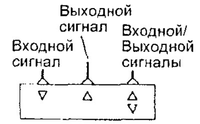
R: When two or more connectors are connected to one device, the terminals of one of the connected connectors are marked with a broken line (-).
S: The broken line (—) indicates that the terminals belong to the same intermediate connector.
T: Indicates the pin number in the connector.
Designations of connectors, connections and components
(The original was published on the website: www.MitsubishiMan.ru)
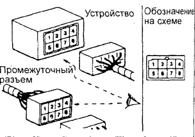
1: Connector designation.
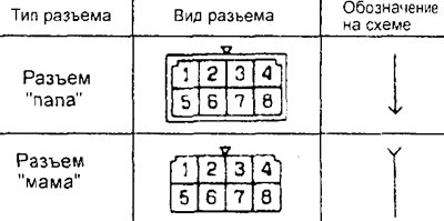
2: Connector pin numbering.
The numbering of the connector terminals from the device side (for an intermediate connector, from the male connector side) is indicated when looking at the connector from the terminal side (from the connector connection side).
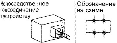
3: Indicates that the harness connector connects directly to the device.
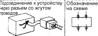
4: Indicates that the harness connector is connected to the device connector that includes the wiring.
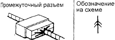
5: Indicates an intermediate connector.
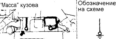
6: Indicates connection to body ground.
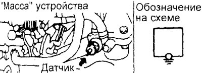
7: Indicates the connection to the device ground (to the device body).
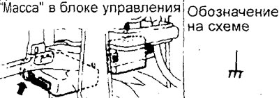
8: Indicates the ground connection inside the electronic control unit.
Connector markings
The connectors are divided into groups according to their location on the vehicle and have symbolic designations.
| Group | Location |
| A | Engine bay |
| IN | Transmission |
| WITH | Front panel and instrument panel |
| D | Floor and roof |
| E | Side doors |
| F | Back door |
Wire marking
Wires differ in the color of the insulation and the cross-section of the conductive part depending on what electrical devices they are connected to.
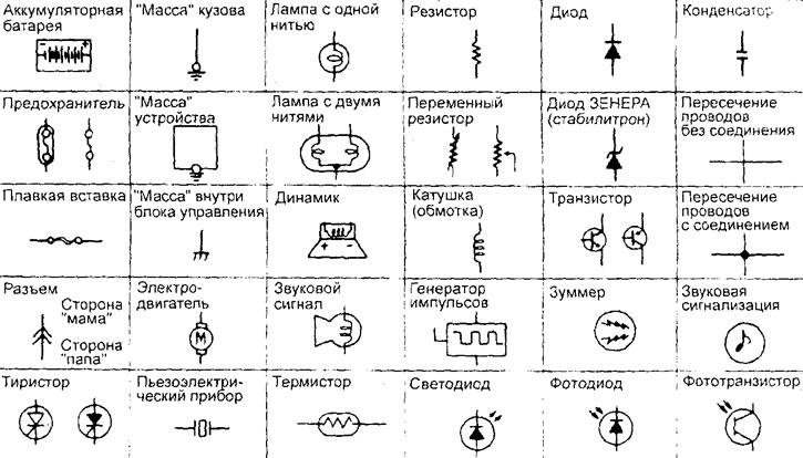
Table of designations of electrical equipment components.
The diagrams indicate the wire marking with a letter code (see figure):

F: Wire type. ("F" flexible wire, "T" twisted wire.)
1.25: Wire cross-section size in mm². (If the value is not specified, the wire cross-section is 0.5 mm². If the wire color code is given in brackets, the wire cross-section is 0.3 mm².)
G: Main color of the wire.
B: Additional wire color.
Color coding
1. Colors of wire insulation, colors of fuse links and fuses.
Note: When the wire insulation color code is two-letter (for example, RG), the first letter indicates the main color of the wire (red), and the second letter indicates the color of the stripe on the wire (green).
| Code | Color | Code | Color |
| IN | black | ABOUT | orange |
| BR | brown | R | pink |
| G | green | R | red |
| GR | grey | V | violet |
| L | blue | W | white |
| LG | light green | Y | yellow |
| SB | blue | TRP | transparent |
2. The electrical circuit used depending on the color of the wire insulation.
| Color | Electrical circuit |
| IN | Starting system and connection to "ground" |
| W | Charger |
| R | Lighting and light signaling |
| G Br | Signal circuits (sensors, etc.) |
| Y | Control devices, lamps, indicators |
| L | Lg | O | Other |
Abbreviations
J/B: Passenger compartment fuse box.
J/C: Jumper connector (located on the front panel)
ACC: The power supply circuit starts to operate when the ignition switch is turned to the "ON" or "ACC" position.
IG1; The power circuit will function even when the ignition switch is turned to the "ST" position.
IG2: Power supply circuit does not function when ignition switch is turned to "ST" position.
GND: "Mass".
ILL: Backlight lamp.
IND: Indicator lamp.